
YSie erhalten ein elektropoliertes Blechgehäuse. Die Oberfläche erscheint unter Werkstattbeleuchtung gleichmäßig und reflektierend. Doch wenn Ihr Qualitätsteam sie mit einem Kontaktprofilometer misst, liegt der Ra-Messwert bei 0,5 µm — höher als der in Ihrer Zeichnung angegebene Höchstwert von 0,38 µm. Ihr Lieferant besteht darauf, dass das Elektropolieren korrekt durchgeführt wurde. Wo liegt also das Problem: am Bauteil oder an der Messung?
Dieses Szenario tritt häufiger auf, als die meisten Einkäufer erwarten. Elektropolierte Oberflächen verhalten sich bei der Profilometermessung anders als mechanisch polierte Oberflächen, und der Grund liegt darin, wie das Messinstrument mit der Oberflächengeometrie interagiert. Dieses Zusammenspiel zu verstehen — und zu wissen, welche Standards, Werkzeuge und Verfahren gelten — ist der Unterschied zwischen zuverlässigen Prüfdaten und wiederkehrenden Streitigkeiten mit Ihrem Lieferanten.
Warum die Prüfung der Oberflächenrauheit elektropolierter Teile nicht einfach ist
Auf einer mechanisch polierten Oberfläche fährt die Profilometernadel über ein Muster gerichteter Kratzer. Die Spitzen und Täler sind regelmäßig, und der Ra-Messwert ist vorhersehbar. Auf einer elektropolierten Oberfläche ist die Situation anders.
Beim Elektropolieren löst ein elektrochemischer Prozess bevorzugt die Spitzen der Metalloberfläche auf und hinterlässt eine mikrog latte, richtungslose Oberfläche. Die Makrotopologie — die größeren Hügel und Täler aus vorheriger Umformung oder Schleifbearbeitung — bleibt weitgehend unverändert. Dies wird oft beschrieben als “die Bäume entfernen, während die Hügel intakt bleiben.”
Hier liegt das Messparadoxon: Eine Standard-Profilometernadel mit einem Spitzenradius von 5 µm kann ungehindert über die mikrog latte elektropolierte Oberfläche fahren und der Makrotopologie folgen, ohne die Mikroebenen-Glättung zu erfassen. Das Ergebnis ist, dass der Ra-Messwert auf einer elektropolierten Oberfläche tatsächlich höher sein kann als der Messwert auf derselben Oberfläche vor dem Elektropolieren — obwohl die Rasterelektronenmikroskopie (REM) bestätigt, dass die elektropolierte Oberfläche objektiv glatter ist.
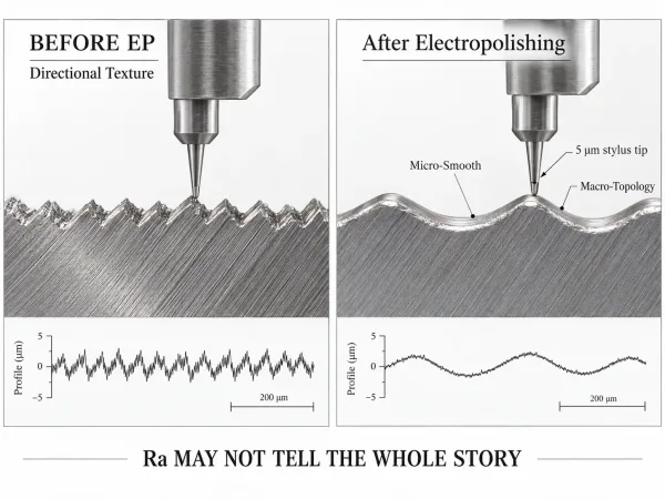
Eine Profilometernadel kann größeren Oberflächenwellen folgen, während sie die durch Elektropolieren erzeugte Mikroebenen-Glättung übersieht.
Das bedeutet nicht, dass das Profilometer defekt ist. Es bedeutet, dass die Messmethode auf den Oberflächenzustand abgestimmt werden muss. Für elektropolierte Teile erfordert dies oft eine Kombination aus Kontaktprofilometrie (mit geeigneten Grenzwellenlängeneinstellungen), berührungsloser optischer Messung und — für kritische Anwendungen — REM- oder Rasterkraftmikroskopie (AFM)-Verifizierung.
Was Ra und Rz tatsächlich messen — und warum Sie beides benötigen
Ra (Mittlere Rauheit) ist das arithmetische Mittel der absoluten Abweichungen des Oberflächenprofils von der Mittellinie über eine festgelegte Messstrecke. Es ist in ISO 4287 definiert und der am weitesten verbreitete Rauheitsparameter in der Fertigung. Ein niedrigerer Ra-Wert weist auf eine glattere Oberfläche hin.
Rz (mittlere maximale Rautiefe) misst den mittleren Höhenunterschied zwischen den fünf höchsten Spitzen und fünf tiefsten Tälern innerhalb der Messstrecke. Im Gegensatz zu Ra, der alle Abweichungen mittelt, erfasst Rz die Extremwerte — was ihn empfindlicher für isolierte tiefe Täler oder scharfe Spitzen macht.
Warum ist das für elektropolierte Oberflächen wichtig? Eine Oberfläche kann einen niedrigen Ra-Durchschnitt aufweisen, aber dennoch isolierte tiefe Täler enthalten, die von vorheriger Bearbeitung oder Schleifen stammen und durch das Elektropolieren nicht vollständig entfernt wurden. Diese Täler sind für Ra unsichtbar, werden aber von Rz erfasst — und sie sind genau die Art von Merkmal, die in pharmazeutischen, lebensmittelverarbeitenden oder Halbleiteranwendungen Kontamination einfängt.
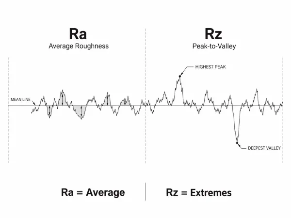
Ra repräsentiert die durchschnittliche Oberflächenabweichung, während Rz größere Spitzen und Täler hervorhebt, die Ra möglicherweise herausmittelt.
| Parameter | Was gemessen wird | Typischer EP-Bereich | Warum es wichtig ist |
|---|---|---|---|
| Ra | Durchschnittliche Abweichung von der Mittellinie | 0,1–0,4 µm (4–16 µin) | Standard-Abnahmekriterium; die meisten Zeichnungen geben Ra an |
| Rz | Mittlere Spitzen-zu-Tal-Höhe | ≤ 1,0 µm | Erfasst isolierte Defekte, die Ra herausmittelt |
| Rq | Quadratischer Mittelwert der Rauheit | Etwas höher als Ra | Empfindlicher gegenüber Ausreißern; wird in einigen Halbleiterspezifikationen verwendet |
Praktische Empfehlung: Für elektropolierte Blechteile, geben Sie Ra als primäres Abnahmekriterium an und fügen Sie Rz als sekundäre Prüfung hinzu, wenn das Teil in kontaminationsempfindlichen Umgebungen eingesetzt wird. Schreiben Sie auf die Zeichnung beide Werte mit ihren Einheiten und der Messnorm, zum Beispiel: “Ra ≤ 0,4 µm nach ISO 4287, Rz ≤ 1,0 µm nach ISO 4287.”
Kontakt- vs. berührungslose Profilometer — So wählen Sie die richtige Methode
Die Wahl zwischen kontaktierender und berührungsloser Messung ist keine Frage, welche “besser” ist — sondern welche Methode zu Ihrer Bauteilgeometrie, Ihrem Oberflächenzustand und Ihrem Prüfzweck passt.
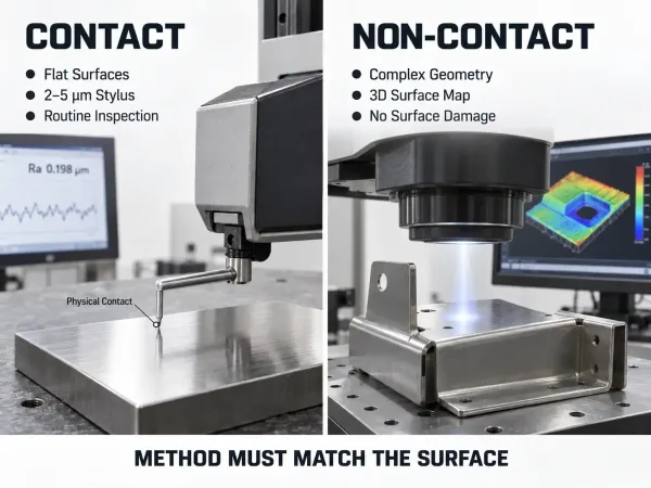
Vergleich von Kontakt-Tastsystem und berührungslosen optischen Methoden zur Messung der Oberflächenrauheit von elektropoliertem Blech.
Tastschnittgerät (Kontakt)
Eine Tastnadel mit Diamantspitze fährt über die Oberfläche und zeichnet die vertikale Verschiebung auf. Dies ist die gebräuchlichste Methode zur Überprüfung der Oberflächenrauheit in der Fertigung.
Wann verwenden: Flache oder leicht gewölbte elektropolierte Oberflächen, bei denen die Tastnadel einen gleichmäßigen Kontakt aufrechterhalten kann. Die meisten Anwendungen in der Werkstatt und bei der Wareneingangsprüfung.
Einschränkungen bei elektropolierten Oberflächen:
- Der Spitzenradius der Tastnadel (typischerweise 2–5 µm) kann die durch Elektropolieren erzeugten mikrog latten Merkmale möglicherweise nicht vollständig auflösen.
- Auf stark reflektierenden elektropolierten Oberflächen kann die Tastnadel über Mikrospitzen “springen” und Messwerte liefern, die die Makrotopologie statt der tatsächlichen Oberflächenbeschaffenheit widerspiegeln.
- Die Tastnadel kann weiche elektropolierte Oberflächen zerkratzen, wenn die Kontaktkraft zu hoch ist.
Optisches Profilometer (berührungslos)
Verwendet Laserinterferometrie, Weißlicht-Scanning oder konfokale Mikroskopie zur Messung der Oberflächentopografie ohne physischen Kontakt.
Wann verwenden: Komplexe Geometrien (Innenflächen, kleine Radien, nahe Schweißzonen), weiche Materialien oder wenn Sie 3D-Oberflächenkartierung anstelle einer Einzellinienmessung benötigen.
Vorteile für elektropolierte Teile:
- No risk of surface damage.
- Higher resolution (down to 0.1 nm for some systems) can resolve the micro-smooth features that a stylus misses.
- Can map surface uniformity across an area, not just along a single trace.
Limitations: Higher equipment cost. Requires trained operators. Surface reflectivity can affect measurement accuracy on mirror-grade electropolished surfaces.
Surface Roughness Comparators
Physical reference samples with known Ra values, used for visual and tactile comparison.
Wann verwenden: Shop-floor screening only. Not suitable for formal acceptance testing of electropolished parts because the visual difference between Ra 0.2 µm and Ra 0.4 µm is invisible to the naked eye.
Recommendation for electropolished sheet metal: Use a contact profilometer as the primary inspection tool with optical profilometry as a secondary or verification method for critical parts. Comparators should only be used for preliminary screening.
Industriestandards für die Oberflächenrauheit elektropolierter Oberflächen
Several standards apply to electropolished surface roughness, each serving a different purpose. Knowing which standard your drawing references — and what it actually requires — prevents misinterpretation during inspection.
| Standard | Scope | What It Defines |
|---|---|---|
| ISO 4287 | Surface texture parameters | Definitions of Ra, Rz, Rq, and other roughness parameters |
| ISO 4288 | Sampling rules | Cutoff length (λc), evaluation length, and number of traces |
| ASME BPE SF1–SF6 | Bioprocessing equipment finishes | Max Ra values for mechanically polished (SF1–SF3) and electropolished (SF4–SF6) surfaces, plus limits on pits, scratches, and inclusions |
| ASTM B912 | Passivation of stainless steel | Requirements for passivation after electropolishing; does not define Ra |
| SEMI F19 | Semiconductor wetted surfaces | Surface finish and passivation requirements for ultra-high-purity applications |
ASME BPE is worth understanding in detail because it goes beyond Ra. Each SF designation (SF4, SF5, SF6 for electropolished surfaces) defines not just a maximum Ra value but also allowable pits, scratches, and inclusions — plus a defined protocol for how measurements are taken. This means an ASME BPE inspection is not a single profilometer reading; it includes visual inspection against defect criteria.
| Designation | Verfahren | Max Ra | Additional Criteria |
|---|---|---|---|
| SF4 | Electropolished | 15 µin (0.38 µm) | Pit, scratch, and inclusion limits per ASME BPE Part SF |
| SF5 | Electropolished | 20 µin (0.51 µm) | Same defect criteria as SF4 |
| SF6 | Electropolished | 25 µin (0.64 µm) | Same defect criteria as SF4 |
Key point for sheet metal buyers: If your drawing references ASME BPE, your supplier must comply with the full acceptance package — not just the Ra number. If your drawing only specifies “Ra ≤ 0.4 µm per ISO 4287,” the inspection is limited to roughness measurement and does not include defect criteria unless you add them separately.
Schritt-für-Schritt-Prüfablauf für elektropolierte Blechteile
The following workflow applies to incoming inspection of electropolished sheet metal parts using a contact profilometer. Adjustments for optical measurement are noted where relevant.
Pre-Measurement Preparation
- Clean the surface. Remove any fingerprints, oil, or residue with a lint-free cloth and isopropyl alcohol. Residual contamination skews Ra readings.
- Stabilize the part. Fix the part on the profilometer stage or a vibration-isolated surface. Movement during measurement invalidates the result.
- Verify instrument calibration. Measure the certified reference specimen before each session. If the reading deviates from the certified value, recalibrate before proceeding.
Selecting Measurement Locations
For electropolished sheet metal parts, measure at the following locations:
- Flat panel areas — the primary acceptance zone; measure at least 3 traces at different orientations.
- Bend zones — electropolishing may not reach the same Ra on the outside of a bend as on flat stock. Measure 2–3 traces near the bend radius.
- Weld-adjacent zones — if the part is welded, measure 10–15 mm from the weld toe. Heat-affected zones may have different surface characteristics.
- Edges and corners — electropolishing is less effective on sharp edges due to current density concentration. Measure if the edge is a functional or cosmetic surface.
Defining Sampling Parameters
Follow ISO 4288 for cutoff length and evaluation length:
| Ra Range (µm) | Cutoff Length λc (mm) | Evaluation Length (mm) |
|---|---|---|
| 0.006–0.02 | 0.08 | 0.4 |
| 0.02–0.1 | 0.25 | 1.25 |
| 0.1–2.0 | 0.8 | 4.0 |
| 2.0–10.0 | 2.5 | 12.5 |
For most electropolished sheet metal parts (Ra 0.1–0.4 µm), the cutoff length is 0.8 mm and the evaluation length is 4.0 mm.
Taking Measurements
- Position the stylus perpendicular to the surface.
- Run at least 3 traces at each measurement location, spaced at least 1 mm apart.
- Calculate the average Ra across all traces at each location.
- If the average exceeds the specification, run additional traces to confirm before declaring non-conformance.
Recording and Reporting
A compliant inspection report should include:
- Part number, drawing revision, and purchase order number
- Measurement instrument model and calibration date
- Measurement locations (reference to drawing or photograph)
- Cutoff length and evaluation length used
- Individual Ra readings and calculated averages
- Rz readings (if specified)
- Accept/reject disposition with reference to the drawing specification
Wenn der Ra-Messwert nicht den Erwartungen entspricht — Fehlerbehebungsleitfaden
An out-of-specification Ra reading does not automatically mean the part is defective. Before rejecting the part or blaming the supplier, work through the following decision tree.
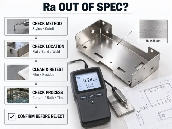
A troubleshooting workflow for identifying measurement, location, contamination, or process causes of out-of-spec Ra readings.
Cause 1: Measurement Method Mismatch
Symptom: Ra reading is higher than expected, but the surface looks and feels smooth.
Likely cause: The stylus tip geometry or cutoff length is not resolving the micro-smooth electropolished features. The profilometer is reading the macro-topology instead of the surface finish.
Action: Switch to a profilometer with a finer stylus tip (2 µm radius) or use optical profilometry. Verify with SEM if available.
Cause 2: Measurement on the Wrong Location
Symptom: Ra is within spec on flat panels but out of spec near bends, welds, or edges.
Likely cause: Electropolishing is less effective in these areas due to current density variations, prior surface damage, or geometric constraints.
Action: Confirm whether the out-of-spec location is within the inspection zone defined on the drawing. If the drawing does not define inspection zones, this is a specification gap that should be addressed in the next revision.
Cause 3: Surface Contamination or Residual Film
Symptom: Ra readings are inconsistent across the same part.
Likely cause: Residual electropolishing film, fingerprints, or packaging residue on the surface.
Action: Clean the surface thoroughly with isopropyl alcohol and re-measure. If readings stabilize, the issue was contamination, not surface finish.
Cause 4: Actual Process Deviation
Symptom: Ra is consistently out of spec across multiple parts, even after confirming measurement method and location.
Likely cause: The electropolishing process itself is out of control — incorrect current density, bath chemistry degradation, insufficient processing time, or temperature deviation.
Action: Request the supplier’s process log for the batch. Compare current density, bath temperature, and processing time against the qualified parameters. If the process data confirms a deviation, the parts may need re-processing.
Key takeaway: Always rule out measurement error before assuming a process failure. The cost of re-measurement is trivial compared to the cost of rejecting a good batch or accepting a bad one.
Was Sie vor der Auftragserteilung bestätigen sollten — Beschaffungs-Checkliste für die Oberflächenrauheit elektropolierter Oberflächen
Most inspection disputes originate not in the shop floor but in the purchase order. If the drawing or RFQ does not clearly define the inspection method, acceptance criteria, and measurement locations, both buyer and supplier are left to interpret the requirement independently — and their interpretations will differ.
Use the following checklist when specifying electropolished surface roughness on your drawings and RFQs:
- Specify Ra with units and tolerance (e.g., Ra ≤ 0.4 µm per ISO 4287). Do not write “smooth finish” or “mirror polish” — these are visual descriptions, not measurable specifications.
- Add Rz as a secondary criterion if the part is used in contamination-sensitive applications (pharmaceutical, food, semiconductor).
- Reference the measurement standard (ISO 4287 for parameters, ISO 4288 for sampling rules). If ASME BPE applies, specify the SF designation.
- Define inspection locations on the drawing — flat areas, bend zones, weld-adjacent zones, and edges. If only certain surfaces require electropolishing, mark them clearly.
- Specify the number of traces per location (minimum 3 recommended).
- Confirm the measurement method with the supplier — contact profilometer, optical profilometer, or both. If the supplier uses a different method than your incoming inspection, readings may not match.
- Define disposition for non-conforming surfaces — rework, reject, or concession. Electropolished parts can sometimes be re-processed, but this depends on the alloy, geometry, and dimensional tolerance remaining.
From our experience: The most common source of inspection disputes we see is a drawing that specifies “Ra ≤ 0.4 µm” without defining the measurement method or location. Two different profilometers — or two different operators — can produce readings 0.1–0.15 µm apart on the same electropolished surface. Specifying the method eliminates this ambiguity.