
You receive an electropolished sheet metal enclosure. The surface looks uniform and reflective under shop lighting. But when your quality team measures it with a contact profilometer, the Ra reading comes back at 0.5 µm — higher than the 0.38 µm maximum your drawing specifies. Your supplier insists the electropolishing was done correctly. So where is the problem: the part, or the measurement?
This scenario plays out more often than most buyers expect. Electropolished surfaces behave differently under profilometer measurement than mechanically polished surfaces, and the reason is rooted in how the measurement instrument interacts with the surface geometry. Understanding this interaction — and knowing which standards, tools, and procedures apply — is the difference between reliable inspection data and recurring disputes with your supplier.
Why Electropolished Surface Roughness Inspection Is Not Straightforward
On a mechanically polished surface, the profilometer stylus traces over a pattern of directional scratches. The peaks and valleys are regular, and the Ra reading is predictable. On an electropolished surface, the situation is different.
During electropolishing, an electrochemical process preferentially dissolves the peaks of the metal surface, leaving behind a micro-smooth, non-directional finish. The macro-topology — the larger hills and valleys from prior forming or grinding — remains largely unchanged. This is often described as “removing the trees while leaving the hills intact.”
Here is the measurement paradox: a standard profilometer stylus with a 5 µm tip radius can travel unimpeded across the micro-smooth electropolished surface, following the macro-topology without detecting the micro-level smoothing. The result is that the Ra reading on an electropolished surface can actually be higher than the reading on the same surface before electropolishing — even though scanning electron microscopy (SEM) confirms the electropolished surface is objectively smoother.
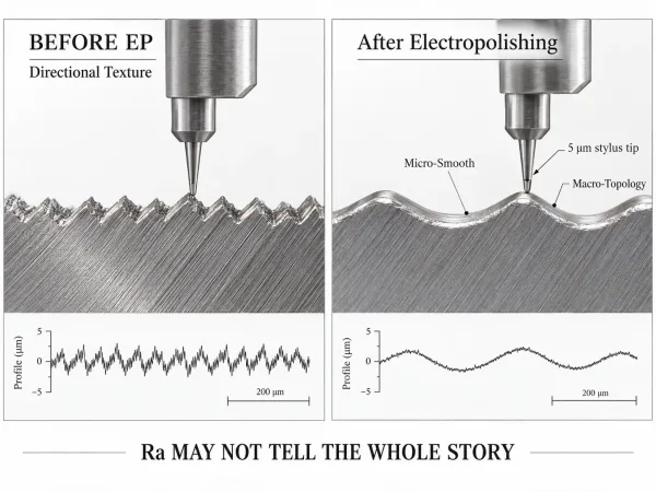
A profilometer stylus can follow larger surface waviness while missing micro-level smoothing created by electropolishing.
This does not mean the profilometer is broken. It means the measurement method must be matched to the surface condition. For electropolished parts, this often requires a combination of contact profilometry (with appropriate cutoff length settings), non-contact optical measurement, and — for critical applications — SEM or atomic force microscopy (AFM) verification.
What Ra and Rz Actually Measure — and Why You Need Both
Ra (Roughness Average) is the arithmetic mean of absolute deviations of the surface profile from the mean line over a specified sampling length. It is defined by ISO 4287 and is the most widely used roughness parameter in manufacturing. A lower Ra value indicates a smoother surface.
Rz (Average Maximum Height) measures the average height difference between the five highest peaks and five deepest valleys within the evaluation length. Unlike Ra, which averages all deviations, Rz captures the extremes — making it more sensitive to isolated deep valleys or sharp peaks.
Why does this matter for electropolished surfaces? A surface can have a low Ra average but still contain isolated deep valleys left by prior machining or grinding that electropolishing did not fully remove. These valleys are invisible to Ra but captured by Rz — and they are exactly the kind of feature that traps contamination in pharmaceutical, food-processing, or semiconductor applications.
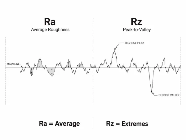
Ra represents average surface deviation, while Rz highlights larger peaks and valleys that Ra may average out.
| Parameter | What It Measures | Typical EP Range | Why It Matters |
|---|---|---|---|
| Ra | Average deviation from mean line | 0.1–0.4 µm (4–16 µin) | Standard acceptance criterion; most drawings specify Ra |
| Rz | Average peak-to-valley height | ≤ 1.0 µm | Catches isolated defects that Ra averages out |
| Rq | Root mean square roughness | Slightly higher than Ra | More sensitive to outliers; used in some semiconductor specs |
Practical guidance: For electropolished sheet metal parts, specify Ra as the primary acceptance criterion and add Rz as a secondary check when the part will be used in contamination-sensitive environments. On the drawing, write both values with their units and the measurement standard, for example: “Ra ≤ 0.4 µm per ISO 4287, Rz ≤ 1.0 µm per ISO 4287.”
Contact vs. Non-Contact Profilometers — How to Choose the Right Method
The choice between contact and non-contact measurement is not about which is “better” — it is about which method matches your part geometry, surface condition, and inspection purpose.
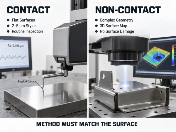
Comparison of contact stylus and non-contact optical methods for measuring electropolished sheet metal surface roughness.
Stylus Profilometer (Contact)
A diamond-tipped stylus traverses the surface and records vertical displacement. This is the most common method for surface roughness verification in manufacturing.
When to use: Flat or gently curved electropolished surfaces where the stylus can maintain consistent contact. Most shop-floor and incoming inspection applications.
Limitations on electropolished surfaces:
- The stylus tip radius (typically 2–5 µm) may not fully resolve the micro-smooth features created by electropolishing.
- On highly reflective electropolished surfaces, the stylus can “skip” across micro-peaks, producing readings that reflect the macro-topology rather than the actual surface finish.
- The stylus can scratch soft electropolished surfaces if the contact force is too high.
Optical Profilometer (Non-Contact)
Uses laser interferometry, white-light scanning, or confocal microscopy to measure surface topography without physical contact.
When to use: Complex geometries (internal surfaces, small radii, near weld zones), soft materials, or when you need 3D surface mapping rather than a single-line trace.
Advantages for electropolished parts:
- No risk of surface damage.
- Higher resolution (down to 0.1 nm for some systems) can resolve the micro-smooth features that a stylus misses.
- Can map surface uniformity across an area, not just along a single trace.
Limitations: Higher equipment cost. Requires trained operators. Surface reflectivity can affect measurement accuracy on mirror-grade electropolished surfaces.
Surface Roughness Comparators
Physical reference samples with known Ra values, used for visual and tactile comparison.
When to use: Shop-floor screening only. Not suitable for formal acceptance testing of electropolished parts because the visual difference between Ra 0.2 µm and Ra 0.4 µm is invisible to the naked eye.
Recommendation for electropolished sheet metal: Use a contact profilometer as the primary inspection tool with optical profilometry as a secondary or verification method for critical parts. Comparators should only be used for preliminary screening.
Industry Standards That Govern Electropolished Surface Roughness
Several standards apply to electropolished surface roughness, each serving a different purpose. Knowing which standard your drawing references — and what it actually requires — prevents misinterpretation during inspection.
| Standard | Scope | What It Defines |
|---|---|---|
| ISO 4287 | Surface texture parameters | Definitions of Ra, Rz, Rq, and other roughness parameters |
| ISO 4288 | Sampling rules | Cutoff length (λc), evaluation length, and number of traces |
| ASME BPE SF1–SF6 | Bioprocessing equipment finishes | Max Ra values for mechanically polished (SF1–SF3) and electropolished (SF4–SF6) surfaces, plus limits on pits, scratches, and inclusions |
| ASTM B912 | Passivation of stainless steel | Requirements for passivation after electropolishing; does not define Ra |
| SEMI F19 | Semiconductor wetted surfaces | Surface finish and passivation requirements for ultra-high-purity applications |
ASME BPE is worth understanding in detail because it goes beyond Ra. Each SF designation (SF4, SF5, SF6 for electropolished surfaces) defines not just a maximum Ra value but also allowable pits, scratches, and inclusions — plus a defined protocol for how measurements are taken. This means an ASME BPE inspection is not a single profilometer reading; it includes visual inspection against defect criteria.
| Designation | Method | Max Ra | Additional Criteria |
|---|---|---|---|
| SF4 | Electropolished | 15 µin (0.38 µm) | Pit, scratch, and inclusion limits per ASME BPE Part SF |
| SF5 | Electropolished | 20 µin (0.51 µm) | Same defect criteria as SF4 |
| SF6 | Electropolished | 25 µin (0.64 µm) | Same defect criteria as SF4 |
Key point for sheet metal buyers: If your drawing references ASME BPE, your supplier must comply with the full acceptance package — not just the Ra number. If your drawing only specifies “Ra ≤ 0.4 µm per ISO 4287,” the inspection is limited to roughness measurement and does not include defect criteria unless you add them separately.
Step-by-Step Inspection Workflow for Electropolished Sheet Metal Parts
The following workflow applies to incoming inspection of electropolished sheet metal parts using a contact profilometer. Adjustments for optical measurement are noted where relevant.
Pre-Measurement Preparation
- Clean the surface. Remove any fingerprints, oil, or residue with a lint-free cloth and isopropyl alcohol. Residual contamination skews Ra readings.
- Stabilize the part. Fix the part on the profilometer stage or a vibration-isolated surface. Movement during measurement invalidates the result.
- Verify instrument calibration. Measure the certified reference specimen before each session. If the reading deviates from the certified value, recalibrate before proceeding.
Selecting Measurement Locations
For electropolished sheet metal parts, measure at the following locations:
- Flat panel areas — the primary acceptance zone; measure at least 3 traces at different orientations.
- Bend zones — electropolishing may not reach the same Ra on the outside of a bend as on flat stock. Measure 2–3 traces near the bend radius.
- Weld-adjacent zones — if the part is welded, measure 10–15 mm from the weld toe. Heat-affected zones may have different surface characteristics.
- Edges and corners — electropolishing is less effective on sharp edges due to current density concentration. Measure if the edge is a functional or cosmetic surface.
Defining Sampling Parameters
Follow ISO 4288 for cutoff length and evaluation length:
| Ra Range (µm) | Cutoff Length λc (mm) | Evaluation Length (mm) |
|---|---|---|
| 0.006–0.02 | 0.08 | 0.4 |
| 0.02–0.1 | 0.25 | 1.25 |
| 0.1–2.0 | 0.8 | 4.0 |
| 2.0–10.0 | 2.5 | 12.5 |
For most electropolished sheet metal parts (Ra 0.1–0.4 µm), the cutoff length is 0.8 mm and the evaluation length is 4.0 mm.
Taking Measurements
- Position the stylus perpendicular to the surface.
- Run at least 3 traces at each measurement location, spaced at least 1 mm apart.
- Calculate the average Ra across all traces at each location.
- If the average exceeds the specification, run additional traces to confirm before declaring non-conformance.
Recording and Reporting
A compliant inspection report should include:
- Part number, drawing revision, and purchase order number
- Measurement instrument model and calibration date
- Measurement locations (reference to drawing or photograph)
- Cutoff length and evaluation length used
- Individual Ra readings and calculated averages
- Rz readings (if specified)
- Accept/reject disposition with reference to the drawing specification
When the Ra Reading Does Not Match Expectations — Troubleshooting Guide
An out-of-specification Ra reading does not automatically mean the part is defective. Before rejecting the part or blaming the supplier, work through the following decision tree.
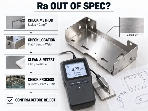
A troubleshooting workflow for identifying measurement, location, contamination, or process causes of out-of-spec Ra readings.
Cause 1: Measurement Method Mismatch
Symptom: Ra reading is higher than expected, but the surface looks and feels smooth.
Likely cause: The stylus tip geometry or cutoff length is not resolving the micro-smooth electropolished features. The profilometer is reading the macro-topology instead of the surface finish.
Action: Switch to a profilometer with a finer stylus tip (2 µm radius) or use optical profilometry. Verify with SEM if available.
Cause 2: Measurement on the Wrong Location
Symptom: Ra is within spec on flat panels but out of spec near bends, welds, or edges.
Likely cause: Electropolishing is less effective in these areas due to current density variations, prior surface damage, or geometric constraints.
Action: Confirm whether the out-of-spec location is within the inspection zone defined on the drawing. If the drawing does not define inspection zones, this is a specification gap that should be addressed in the next revision.
Cause 3: Surface Contamination or Residual Film
Symptom: Ra readings are inconsistent across the same part.
Likely cause: Residual electropolishing film, fingerprints, or packaging residue on the surface.
Action: Clean the surface thoroughly with isopropyl alcohol and re-measure. If readings stabilize, the issue was contamination, not surface finish.
Cause 4: Actual Process Deviation
Symptom: Ra is consistently out of spec across multiple parts, even after confirming measurement method and location.
Likely cause: The electropolishing process itself is out of control — incorrect current density, bath chemistry degradation, insufficient processing time, or temperature deviation.
Action: Request the supplier’s process log for the batch. Compare current density, bath temperature, and processing time against the qualified parameters. If the process data confirms a deviation, the parts may need re-processing.
Key takeaway: Always rule out measurement error before assuming a process failure. The cost of re-measurement is trivial compared to the cost of rejecting a good batch or accepting a bad one.
What to Confirm Before You Place the Order — Procurement Checklist for Electropolished Surface Roughness
Most inspection disputes originate not in the shop floor but in the purchase order. If the drawing or RFQ does not clearly define the inspection method, acceptance criteria, and measurement locations, both buyer and supplier are left to interpret the requirement independently — and their interpretations will differ.
Use the following checklist when specifying electropolished surface roughness on your drawings and RFQs:
- Specify Ra with units and tolerance (e.g., Ra ≤ 0.4 µm per ISO 4287). Do not write “smooth finish” or “mirror polish” — these are visual descriptions, not measurable specifications.
- Add Rz as a secondary criterion if the part is used in contamination-sensitive applications (pharmaceutical, food, semiconductor).
- Reference the measurement standard (ISO 4287 for parameters, ISO 4288 for sampling rules). If ASME BPE applies, specify the SF designation.
- Define inspection locations on the drawing — flat areas, bend zones, weld-adjacent zones, and edges. If only certain surfaces require electropolishing, mark them clearly.
- Specify the number of traces per location (minimum 3 recommended).
- Confirm the measurement method with the supplier — contact profilometer, optical profilometer, or both. If the supplier uses a different method than your incoming inspection, readings may not match.
- Define disposition for non-conforming surfaces — rework, reject, or concession. Electropolished parts can sometimes be re-processed, but this depends on the alloy, geometry, and dimensional tolerance remaining.
From our experience: The most common source of inspection disputes we see is a drawing that specifies “Ra ≤ 0.4 µm” without defining the measurement method or location. Two different profilometers — or two different operators — can produce readings 0.1–0.15 µm apart on the same electropolished surface. Specifying the method eliminates this ambiguity.