
A bracket drawing shows R0.030″ for 6061-T6 aluminum. The fabricator’s first question: will this crack? Their second: do we need custom tooling? The engineer specified a standard radius — the same one used on the mild steel version — and assumed it would carry over. It did not. The outer surface cracked on the first test bend, and the punch nose that produced clean bends in mild steel could not form the aluminum without exceeding its elongation limit. The fix required a larger radius, a different die opening, and a revised flat pattern. The part shipped three weeks late.
This scenario is more common than most engineers expect. The minimum inside radius note on a sheet metal drawing is one of the most frequently misunderstood callouts in fabrication. Engineers either skip it entirely — leaving the fabricator to guess — or specify it in a way that forces custom tooling, cracking, or unnecessary cost. The correct approach is neither extreme. It starts with understanding what fabricators do when the note is missing, and then deciding whether your part actually needs one.
What Is a Minimum Inside Radius Note on a Sheet Metal Drawing?
A minimum inside radius note is a callout that specifies the smallest acceptable inside curve radius for a bent feature on a sheet metal part. The inside radius is measured from the inner surface of the bend to the center of curvature — not the outer surface. This distinction matters because the outer surface stretches during bending and the inner surface compresses. Material failure, when it occurs, happens on the outside.
The note typically appears in one of two places on a drawing:
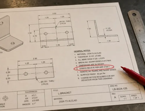
General Notes block. A line such as “1. INSIDE BEND RADIUS: R0.125 MIN PER BEND” placed in the title block area. This applies to every bend on the part unless a specific bend has its own callout.
Bend-specific callout. A leader line pointing to an individual bend with a radius value and tolerance — for example, “R0.125 ±0.010” — placed near the bend line symbol.
In both cases, the note tells the fabricator: do not produce an inside radius smaller than this value. Anything equal to or larger is acceptable, unless an upper limit is also specified.
Inside Radius vs Outside Radius
The industry convention is to specify the inside radius. When a drawing says “R0.125,” it means the inside measurement. Some drawings — particularly older ones or those following certain European conventions — may reference the outside radius, which equals the inside radius plus material thickness. If the convention is not stated, fabricators assume inside radius. When in doubt, add “INSIDE” to the callout to eliminate ambiguity.
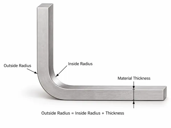
Diagram showing the difference between inside and outside bend radius on sheet metal.
How Fabricators Read Your Radius Note — or Its Absence
When a sheet metal drawing arrives at a fabrication shop, the engineering team evaluates it in a specific order. Material and thickness come first. Then bend count, bend angles, and flange lengths. The radius note — or its absence — is assessed alongside these variables.
The Fabricator’s Default Decision Tree
If the drawing specifies a radius, the fabricator compares it against their standard tooling. Most press brake shops stock punch noses in common increments: 0.015″, 0.030″, 0.050″, 0.062″, 0.125″. If the specified radius matches a standard punch, production proceeds. If it does not — for example, the drawing calls for R0.040″ and the shop only has 0.030″ and 0.050″ — the fabricator must either order custom tooling, use the closest available radius and request approval, or push back on the specification.
If the drawing does not specify a radius, the fabricator uses a default based on material and sheet metal thickness. For mild steel, the default is typically 1× the material thickness. For stainless steel (304), it is 1.5× to 2× thickness. For aluminum 5052, about 1× thickness. For aluminum 6061-T6, 2× to 3× thickness. These defaults are not arbitrary — they reflect the minimum radius that standard tooling can produce without cracking the material.
The default is also influenced by the die opening. In press brake air bending, the inside radius forms as a percentage of the V-die opening — typically 15% to 20% for mild steel, 20% to 22% for stainless steel. The fabricator selects the die opening based on material thickness (usually 6× to 12× the thickness), and the resulting radius is a natural consequence of that choice.
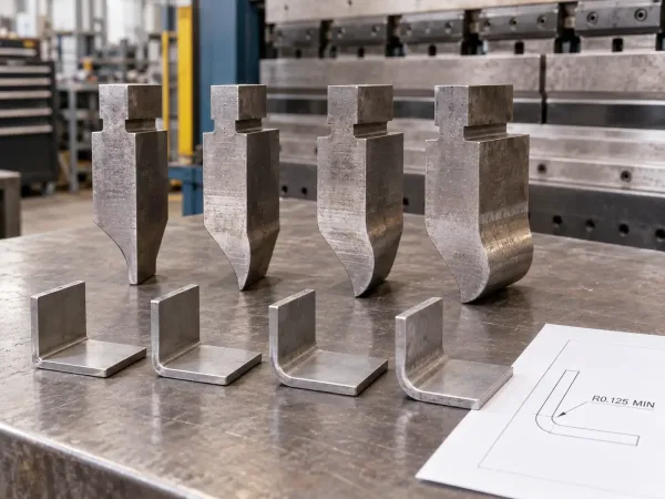
Standard press brake punches and bent samples showing how tooling influences bend radius.
Why “No Note” Can Be Safer Than “Wrong Note”
An unspecified radius gives the fabricator the flexibility to select tooling that matches their equipment and produces a clean bend. A specified radius that does not match available tooling forces one of three outcomes: custom tooling (added cost and lead time), a negotiation to revise the specification (added communication and delay), or a rejected RFQ (the fabricator declines the job).
This does not mean you should never specify a radius. It means you should specify it when there is a functional reason — and leave it open when there is not.
When You Must Specify — and When You Can Leave It Blank
The decision to add a minimum inside radius note depends on whether the radius affects the part’s fit, function, or appearance. The matrix below covers common scenarios.
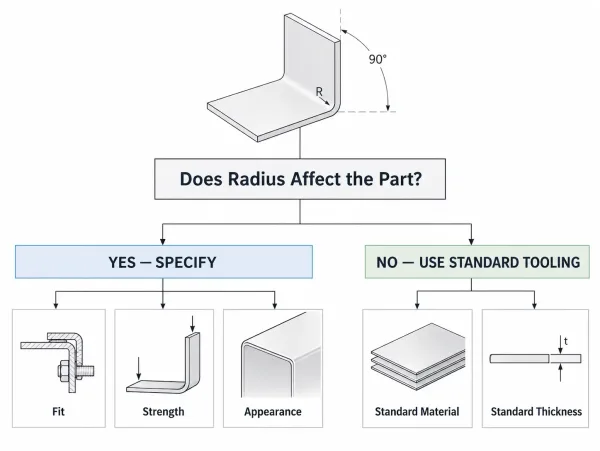
Decision guide showing when a bend radius should be specified or left to standard tooling.
| Scenario | Specify? | Reason |
|---|---|---|
| Radius affects assembly clearance (e.g., part fits inside another component) | Yes | A larger-than-expected radius may cause interference |
| Radius affects structural strength or fatigue life | Yes | Tighter radii increase stress concentration at the bend |
| Radius is a cosmetic requirement (visible bend surface) | Yes | Inconsistent radii on visible parts look unprofessional |
| Customer or industry standard requires a specific radius | Yes | Compliance with ASTM, ISO, or customer specification |
| Radius does not affect fit, function, or appearance | No | Let the fabricator use their standard tooling |
| Part uses common material at standard thickness | No | Fabricator’s default radius is usually correct |
The Gray Area: “Preferred” vs “Required” Radius
Some drawings use “PREFERRED” instead of “MIN” in the radius callout — for example, “R0.125 PREFERRED.” This signals that the radius is the design intent but allows the fabricator to deviate if their tooling does not match. It is a middle ground between specifying and omitting.
The risk with “PREFERRED” is that it is not always interpreted consistently. Some fabricators treat it as a hard requirement; others treat it as a suggestion. If the radius matters, use “MIN” (or a tolerance like “R0.125 ±0.010”). If it does not, leave the callout out entirely.
The Correct Format: How to Write a Radius Callout
Most radius callouts follow one of three formats, depending on where they appear on the 2D sheet metal drawing and how much precision is required.
General Notes Format
The most common approach is a single line in the General Notes block:
1. INSIDE BEND RADIUS: R0.125 MIN PER BEND
This applies to every bend on the part. If some bends require a different radius, those bends get individual callouts that override the general note.
Callout Format on Bend Lines
For individual bends, the radius is placed near the bend line symbol with a leader:
R0.125 MIN
or, with a tolerance:
R0.125 ±0.010
The leader points to the inside of the bend. The callout should be close enough to the bend line to be unambiguous, but not so close that it crowds other annotations.
Adding Tolerance to the Radius
A radius without a tolerance gives the fabricator no precision target. “R0.125 MIN” means anything from 0.125″ to infinity is acceptable. For most parts, this is fine — the fabricator’s standard tooling will produce a consistent radius within a few thousandths of an inch.
When the radius must be held within a specific range — for example, to maintain consistent stress distribution across multiple bends — add a bilateral tolerance: “R0.125 ±0.010.” This tells the fabricator the acceptable range is 0.115″ to 0.135″.
Be cautious with tight radius tolerances. Holding ±0.005″ on a bend radius requires test bends, manual adjustment, and first-article inspection. That adds cost and lead time. For most applications, ±0.010″ or ±0.020″ is sufficient.
How the Radius Note Affects Cost, Tooling, and Lead Time
Specifying a radius that does not match the fabricator’s standard tooling has direct consequences. In sheet metal DFM, understanding those consequences helps you make informed decisions about when to specify the radius and how tightly to hold the value.
When Your Radius Doesn’t Match Standard Tooling
If your drawing calls for R0.030″ and the fabricator’s standard punch nose is 0.050″, the shop has three options:
- Order a custom punch nose. This typically costs $500 to $2,000+ depending on the punch length and material. Lead time is usually 2 to 4 weeks.
- Use the closest standard radius and request approval. The fabricator asks whether R0.050″ is acceptable instead of R0.030″. This adds 1 to 3 days of communication.
- Decline the RFQ. If the radius is a hard requirement and the shop cannot justify custom tooling for the order quantity, they may pass on the job.
For prototype or low-volume orders (1 to 50 pieces), custom tooling is rarely cost-effective. The fabricator will almost always ask to use a standard radius or request a revision.
The Hidden Cost of Tight Radius + Tight Tolerance
Specifying both a tight radius and a tight tolerance compounds the difficulty. A drawing that calls for R0.030″ ±0.005″ in stainless steel is asking for a combination that requires:
- A specific punch nose radius (likely custom)
- A controlled die opening (not all V-die widths produce the target radius)
- Test bends on the actual material lot (springback varies by batch)
- First-article inspection with radius measurement (using a radius gauge or optical comparator)
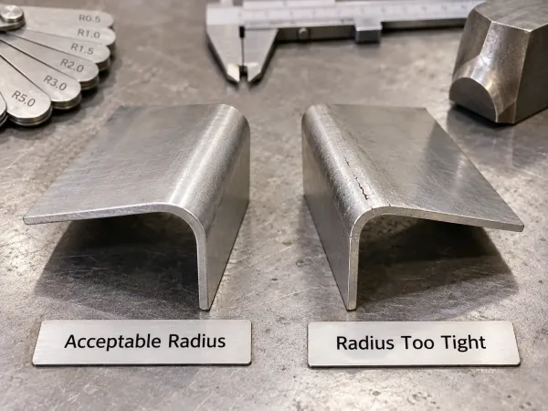
Close-up comparison of an acceptable bend and a cracked bend caused by an excessively tight radius.
Each of these steps adds time and cost. The interaction between radius and angle tolerance is particularly important: a tighter radius increases springback, which makes the bend angle harder to control. Specifying R0.030″ and ±0.5° on the same bend may require multiple trial bends to dial in the overbend angle.
Material Matters: Why the Same Note Produces Different Results
The same radius value produces very different outcomes depending on the material. R0.060″ is a standard, tooling-friendly radius for 16-gauge mild steel. The same R0.060″ in 16-gauge 6061-T6 aluminum is below the material’s minimum bend radius and will almost certainly crack.
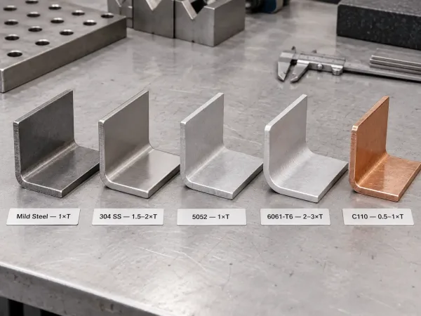
Bent samples showing how minimum bend radius varies by sheet metal material.
Quick Reference Table
| Material | Minimum Radius (× Thickness) | For 0.060″ (16 ga) Sheet | Notes |
|---|---|---|---|
| Mild Steel (CRS) | 1× T | 0.060″ | Most forgiving; standard tooling covers this |
| Stainless Steel 304 | 1.5–2× T | 0.090″–0.120″ | Higher springback; requires overbending |
| Aluminum 5052-H32 | 1× T | 0.060″ | Good formability; similar to mild steel |
| Aluminum 6061-T6 | 2–3× T | 0.120″–0.180″ | Prone to cracking; anneal for tighter bends |
| Copper (C110, soft) | 0.5–1× T | 0.030″–0.060″ | Very ductile; tight radii achievable |
The table above shows starting-point values for air bending. Actual minimums depend on the alloy temper, grain direction, die opening, and punch nose radius. Always verify against your material supplier’s data.
Grain Direction: The Variable Most Drawings Ignore
Sheet metal develops a directional grain structure during rolling. Bending perpendicular to the grain (across the rolling direction) allows tighter radii than bending parallel to it. For most mild steel parts, grain direction is not critical and is not called out on drawings. For high-strength alloys, parts near the minimum radius limit, or parts with fatigue requirements, specifying grain direction can prevent cracking.
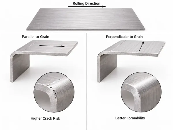
Diagram comparing bends parallel and perpendicular to sheet metal rolling direction.
When grain direction matters, add a note such as:
BEND LINE PERPENDICULAR TO ROLLING DIRECTION
This gives the fabricator a clear constraint and prevents them from nesting the flat pattern in a direction that puts the bend line parallel to the grain.
FAQ
Send Us Your Drawings for a DFM Review
If you are unsure whether your radius callout matches available tooling — or whether you need one at all — send your drawings to SR-MFG for a DFM review. Our engineering team will evaluate your bend specifications against our standard tooling and flag any radius, tolerance, or material conflicts before quoting. Typical turnaround is within 24 hours.