Home -> Service -> Sheet Metal Finishing -> Powder Coating
Powder Coating Services for Metal Parts
SR MFG provides industrial-grade powder coating solutions for manufacturers worldwide, with a focus on production consistency, inspection traceability, and on-time delivery. From prototypes to full-scale production, every part is processed under standardized procedures with end-to-end data traceability—and delivery timelines can be written into the contract to ensure schedule adherence.
SR MFG’s Three Non-Negotiable Commitments
- Typical film thickness: 60 ± 10 μm; critical assembly/mating surfaces can be masked or controlled for reduced build.
- Color consistency: Production is matched to the approved reference sample; color is measured under standard lighting, with project-specific ΔE targets (down to ≤ 1.0 when required).
- Corrosion validation: Salt spray testing available per ASTM B117 / ISO 9227; acceptance per customer criteria (e.g., red rust, blistering, scribe creep).
Why Powder Coat Sheet Metal?
Many sheet metals—such as carbon steel and low-alloy steel—will oxidize and corrode when left unprotected, especially in environments with humidity, condensation, or salt spray. Over time, rust doesn’t just hurt appearance; it can also reduce structural integrity and shorten service life. Powder coating forms a dense, durable protective layer on the metal surface, significantly improving corrosion resistance and wear resistance while reducing issues like rusting, chipping, and paint peel.
For industrial products, the value of powder coating goes far beyond “adding color.” It’s a practical way to prevent corrosion, slow aging, and improve long-term durability. With consistent cosmetic results and better protection, powder coating helps extend product life, reduce rework and warranty risk, and ultimately lower total cost of ownership.
It’s especially well-suited for parts that need both strong corrosion protection and consistent appearance—such as outdoor equipment housings, electrical cabinets/enclosures, industrial brackets, and structural components.

What Is Powder Coating?

Powder coating is a widely used finishing process in sheet metal fabrication that creates a dense, durable protective layer on the metal surface.
Before coating, the parts go through the appropriate pretreatment based on the material—such as degreasing, cleaning, and (when required) pickling—to improve adhesion and corrosion resistance. The powder is then applied evenly to the metal surface using a spray gun.
The “powder” itself is a formulated blend of resins, pigments, fillers, and curing agents. Under an electrostatic charge, the powder is attracted to and held on the grounded workpiece.
After application, the parts are cured in an oven—typically 180–200°C (per the powder supplier’s technical data sheet). During curing, the powder melts, flows out, and crosslinks to form a continuous film.
This coating process not only improves wear resistance and corrosion protection, but also enhances the overall appearance of the part.
SR MFG Powder Coating Capabilities
SR MFG Metal Coating & Surface Finishing Production Line
| Category | Item | Customer-Friendly Description (Recommended) |
|---|---|---|
| Basic Specs | Maximum coatable part size | Up to L 6000 × H 2400 × W 700 mm, defined by hanger orientation and the effective dimensions of the spray booth and curing oven. |
| Basic Specs | Maximum part weight | Up to 200 kg per piece. Oversized structural parts can be evaluated with a split/sub-assembly approach (subject to seam appearance and assembly method). |
| Basic Specs | Typical coating thickness range | 50–100 μm, set based on product requirements and service environment. |
| Basic Specs | Recommended target thickness | 60–80 μm for a balanced mix of corrosion protection and cost; tighter targets available for critical programs. |
| Powder System Options | Epoxy | Best for indoor corrosion and chemical resistance (e.g., equipment frames, indoor structural parts). Not recommended for long-term outdoor UV exposure. |
| Powder System Options | Polyester | General-purpose outdoor weather resistance (fences, outdoor brackets, cabinet/enclosure shells). |
| Powder System Options | Epoxy/Polyester Hybrid | Versatile for indoor/outdoor use with good appearance and value; outdoor life targets should be defined in advance. |
| Powder System Options | Super-Durable / High-Performance | Super-durable polyester (AAMA 2604) / high-performance systems (AAMA 2605), selected based on required service life and weathering targets. |
| Appearance Capabilities | Surface effects | Matte, gloss, sand texture, metallic, hammer tone, and more—confirmed by color chips and sample runs. |
| Appearance Capabilities | Color range | RAL / Pantone matching available. Final production is controlled to the approved sample (metallic/pearl effects may have limitations). |
| Appearance Capabilities | Color changeover time | Standard color changeover ≤ 30 minutes; metallic/special-effect colors ≤ 60 minutes (depends on production scheduling). |
| Appearance Capabilities | Minimum order quantity | 100 pcs per batch (negotiable for small runs; custom colors may be affected by powder supplier MOQ). |
| Capacity & Lead Time | Capacity | Capacity depends on part surface area, rack density, and changeover frequency. We can calculate capacity from your drawings and commit it in the quotation. |
| Capacity & Lead Time | Standard lead time | Typically 3–7 days, depending on quantity and complexity. |
| Capacity & Lead Time | Expedite policy | Expedited scheduling is available, subject to inspection cadence and risk controls. Expedite fees may apply. |
| Masking & Protection | Threaded holes | High-temperature silicone plugs and masking tape to keep threads clean and assembly-ready. |
| Masking & Protection | Grounding points | Dedicated masked/no-coat areas to maintain electrical conductivity for grounding. |
| Masking & Protection | Mating surfaces | High-temperature masking film to prevent coating thickness from affecting fit and assembly accuracy. |
| Quality & Validation | Thickness control | Coating thickness can be measured per ASTM D7091 (calibration/verification/adjustment + compliant measurement) with records provided. |
| Quality & Validation | Adhesion | Sample-based adhesion testing per ASTM D3359 (cross-hatch) with results provided. |
| Quality & Validation | Corrosion resistance | Salt spray testing available per ASTM B117 (and others as required). Acceptance criteria (red rust, blistering, scribe creep, etc.) follow customer specs or mutual agreement. |
How to Choose the Right Powder Coating System
| Service Environment (Reference) | Recommended Topcoat Powder | Recommended System Build | SR MFG Recommended DFT | Example Parts | Suggested Acceptance / Validation (Optional) |
|---|---|---|---|---|---|
| Indoor, no UV (C1–C2) | Epoxy or Epoxy-Polyester Hybrid | Single coat | 60–80 μm (adjustable within 50–100 μm) | Indoor cabinets/enclosures, brackets, equipment frames | DFT, adhesion, appearance; chemical and abrasion resistance if required |
| General outdoor, UV exposure (C2–C3) | Polyester (TGIC or HAA) | Single coat (add primer/base coat for higher corrosion targets) | 70–100 μm (set to life target) | Outdoor covers, fences, door/window hardware, outdoor brackets | DFT, adhesion, salt spray or cyclic corrosion testing (define “hours + acceptance criteria” per project spec) |
| Coastal / heavy corrosion (C4–C5) | Topcoat: Polyester or Super-durable Polyester | Two-coat system preferred (anti-corrosion primer + weatherable topcoat) | Total 120–200 μm (project-specific) | Coastal cabinets, industrial frames, parts exposed to salt spray/high humidity | Strongly recommended: cyclic corrosion testing with clear acceptance criteria (scribe creep, blister rating, etc.) |
| Architectural exterior (high weathering resistance) | Super-durable Polyester (aligned with AAMA 2604) | Per specification (often single coat) | Per specification (typically ≥30 μm, depending on system) | Architectural exterior components, façade accessories, decorative panels | Test to AAMA 2604 requirements (color shift, gloss retention, etc.) |
| Premium architectural / ultra-long-life exterior | High-performance system aligned with AAMA 2605 | Per specification (may be multi-coat) | Per specification | Landmark projects with stringent long-term color/gloss retention requirements | Test to AAMA 2605 requirements (more demanding exposure/performance criteria) |
Notes on Standards
SR MFG can verify DFT, adhesion, salt spray, weathering, and related performance using ISO/ASTM-equivalent methods.
For accelerated tests such as salt spray and weathering, the order should clearly define the test method, duration,
and acceptance criteria. Final acceptance follows the customer’s specification or the mutually signed inspection standard.
C1–C5 refer to atmospheric corrosivity categories defined in ISO 12944.
SR MFG Powder Coating Process Flow

01.Surface Pretreatment
Degreasing and cleaning; rust removal as needed based on the material and surface condition.
02.Surface Touch-Up (Optional)
For parts with visible dents, pits, or weld imperfections, we can apply filler and sand smooth for cosmetic applications.
03.Masking
High-temperature tape/plugs are applied to areas that must remain uncoated (mating surfaces, threads, grounding points, etc.).
04.Preheating (Optional)
Parts may be preheated to build higher film thickness or improve coverage, depending on process requirements.
05.Electrostatic Powder Application
Powder is applied evenly to the grounded part using electrostatic spray guns.
06.Oven Curing
Cured per the powder supplier’s TDS (typically 180–200°C, depending on the powder system).
Challenging Parts & Design Recommendations
Common “Difficult” Part Types
In powder coating, the biggest challenges typically come from deep recesses and inside corners (Faraday effect), sharp-edge coverage, drainage/venting for enclosed cavities, and outgassing pinholes on substrates such as castings or galvanized parts. SR MFG recommends addressing these risks early in the design phase—by adding radii and deburring, adding drain/vent holes, clearly defining masking for functional surfaces, and using pre-bake/outgas strategies when needed—to improve first-pass yield and production consistency.
These geometries are prone to the Faraday cage effect: powder is attracted to outer edges, while inside corners and deep channels end up with light coverage or bare spots.
Sharp edges are common weak points—film build is often thinner and corrosion protection is reduced. Adding radii and removing burrs significantly improves edge coverage and corrosion performance.
If parts don’t have proper drain and vent paths, pretreatment chemicals and rinse water can remain trapped. Residual liquid can lead to incomplete drying, blistering, corrosion, or coating defects. Industry guidance typically recommends properly placed drain/vent holes for enclosed or semi-enclosed designs.
During curing, gas released from pores can create pinholes or crater defects (“volcanoes”). A pre-bake/outgas bake is a common countermeasure.
Cure temperatures and hanging methods can amplify warping and oil-canning. Large parts are also more sensitive to grounding and spray coverage—non-uniform film build is more common.
These areas often require masking or thickness limits; otherwise the coating can interfere with fit, conductivity, torque requirements, or tolerance stack-up.
Design Recommendations
- Avoid deep, narrow channels and cavities whenever possible—ensure the spray gun has “line of sight” and room to aim (larger openings and shallower depths are better).
- Add inside radii or soften corners to improve electric field distribution and help powder reach the recesses.
- If geometry can’t be changed, note on the drawing that touch-up/secondary coating in recesses is acceptable, or allow a lower cosmetic grade in those zones.
- Recess areas often require lower voltage/microamps, adjusted spray angles, or equipment/powder better suited for deep cavities.
Deburr and break edges / add radii. The sharper the edge, the harder it is to achieve stable film build. A radius dramatically improves edge coverage and corrosion resistance.
-
Design drain and vent holes so pretreatment solution, rinse water, and condensation can escape and the part can dry quickly.
-
Place holes near the closed end / lowest point to aid drainage. In some cases, keeping one end open is the simplest solution—if cosmetics allow.
-
Outgas bake (pre-bake): heat the part above the coating’s required PMT (Part Metal Temperature) and hold to drive off trapped gases before coating (a widely recommended approach by powder/material suppliers).
-
When necessary, use a primer/sealer base coat to “seal” porosity before applying the topcoat—especially common for porous castings.
-
Clearly define on the drawing which areas are no-coat, thickness-limited, and where racking/hanging points are acceptable (threads, mating surfaces, grounding points).
-
Provide process allowance for masking—for example, add a small masking step or flange so the masking edge doesn’t land on a Class A cosmetic surface.
These areas often require masking or thickness limits; otherwise the coating can interfere with fit, conductivity, torque requirements, or tolerance stack-up.
Common Powder Coating Defects & Prevention
This section summarizes the most common powder-coating defects—such as uneven coverage, cratering/fisheyes, pinholes/blistering, orange peel, and thin film in recessed areas caused by the Faraday effect—and provides a practical checklist for each: “root causes → prevention keys → quick corrective actions.” It’s designed to help reduce rework and risk during both sampling and mass production.
Visible symptoms: thin spots, striping, inconsistent spray output (spray “pulsing” or surging)
Primary causes:
-
Unstable powder fluidization (porous plate issues, incorrect fluidizing air settings, powder moisture pickup, improper powder level or poor agitation)
-
Air/powder path restrictions (kinked hoses, powder build-up in the venturi/nozzle, impact fusion)
-
Nozzle/hosing mismatch (wrong nozzle type, hose diameter/length not matched to the gun/pump setup)
Corrective actions:
-
Verify and restore proper fluidization (dry the air supply; balance fluidizing air vs. atomizing air).
-
Clean or replace the nozzle, venturi, and hoses; check hose length and minimum bend radius.
-
Switch to a more suitable nozzle/attachment if required by the part geometry or powder type.
Prevention & process control:
-
Set routine checks for: compressed-air dryness/filtration, hose installation standards (length/bends), and gun electrode/nozzle cleaning intervals.
-
Control powder storage conditions and reclaimed-to-virgin powder ratio.
-
Add “powder cloud uniformity” to the start-up first-piece checklist.
Visible symptoms: excessive overspray, powder won’t “stick,” high powder consumption
Primary causes:
-
Gun output issues (low kV, contaminated/worn electrode)
-
Poor grounding (racks/hooks contaminated → higher resistance)
-
Airflow too high (gun air volume or booth exhaust pulling powder away)
-
Incorrect settings (kV/µA too low or too high)
Corrective actions:
-
Verify kV output and inspect the electrode; clean or replace as needed.
-
Clean racks/hooks and verify electrical continuity.
-
Reduce unnecessary spray air and optimize booth airflow.
-
Tune kV and current limit (µA) to part geometry and coverage needs.
Prevention & process control:
-
Many process guidelines reference ~50–100 kV as a common working range; µA control is often the key variable—too high can cause saturation and back-ionization (exact ranges depend on equipment and powder).
-
Use a megohmmeter to measure part-to-ground resistance, targeting ≤ 1 MΩ.
-
Powder build-up on racks/hooks/chains can significantly increase resistance—include these in a defined cleaning cycle.
Visible symptoms: small circular “dimples” or craters—often looks like oil repelling the coating
Primary causes:
-
Low-surface-energy contamination: silicone, oils/lubricants, hand lotion, mold-release agents
-
Oil/water in compressed air
-
Cross-contamination: mixed powder lots, foreign particles (including silicone-bearing dust)
-
Booth/oven dust fallout onto parts
Corrective actions:
-
Trace the contamination source (compressed air, wipes/rags, booth fixtures, tooling, blasting media).
-
Stop using any suspect reclaimed powder or mixed powder streams.
-
Improve housekeeping—vacuum rather than blow off to avoid re-aerosolizing dust.
Prevention & process control:
-
Implement a “silicone-free” control plan (segregate silicone oils, release agents, silicone-based cleaners; dedicate wipes and gloves).
-
Use dried, oil-removed compressed air (dryer + coalescing/oil filters).
-
Clean booths/ovens primarily by vacuuming to reduce airborne dust.
-
Include reclaimed/virgin ratio and sieve/filter condition in routine checks to prevent debris and silicone dust contamination.
Visible symptoms: pinholes, bubbles, blisters—more noticeable on light colors
Primary causes:
-
Outgassing / volatiles (castings, weld porosity, porous substrates; galvanized parts where zinc layers release gas/moisture)
-
Residual moisture after pretreatment (insufficient drying)
-
Rapid heat-up or excessive film build that traps gas during cure
Corrective actions:
-
Run a pre-bake / outgas bake to drive off gas/moisture.
-
Ensure parts are fully dried after wash/rinse.
-
Optimize the heat-up curve to allow venting during melt/flow; avoid excessive film build.
-
If needed, use an outgas-resistant powder system or additives designed for outgassing substrates.
Prevention & process control:
-
Evaluate substrate type (cast, galvanized, welded) alongside the required cosmetic grade.
-
Emphasize curing to verified Part Metal Temperature (PMT) and record cure profiles.
-
Control film thickness—avoid “one-pass too thick” builds.
Visible symptoms: textured “orange peel” appearance, poor flow-out, waviness
Primary causes:
-
Powder formulation/flow characteristics
-
Film build too high
-
Incorrect cure window (ramp/soak not matched to the powder TDS)
-
Overspray/powder pile-up, sometimes accompanied by back-ionization or repulsion
Corrective actions:
-
Control film thickness (avoid localized pile-up).
-
Adjust cure settings per the powder supplier’s TDS.
-
Optimize gun distance, stroke pattern, and parameters to reduce overspray concentration.
-
Switch to a more suitable powder system if required.
Prevention & process control:
-
Track and correlate film thickness vs. appearance in inspection records to define your best process window.
-
For complex parts, standardize the Class A surface orientation, racking direction, and spray path.
Visible symptoms: thin film or bare spots in inside corners/recesses; outer surfaces become overly thick
Primary causes:
-
Electric field lines naturally favor the nearest grounded surfaces and “avoid” deep recesses.
-
Excessive kV/µA, too-close gun distance, or too much powder output increases edge build and repulsion—making recess coverage even harder.
-
Simply “cranking up air pressure” can blow off powder that has already deposited.
Corrective actions:
-
Reduce kV first and/or limit µA, then adjust nozzle/spray pattern and gun angle.
-
Slightly higher powder velocity can help push powder into recesses, but avoid blow-off—tune together with electrical settings.
-
If necessary, consider process/equipment options better suited for complex geometry (e.g., tribo or pulse control, depending on your system).
Prevention & process control:
-
Both corona and tribo are electrostatic methods—the difference is the charging mechanism. Tribo may perform better in certain deep-recess geometries because it doesn’t create the same ion field, but it still must be validated for the specific powder and part geometry.
Quick Troubleshooting Order (Recommended)
Air quality (dry/oil-free/filtered) → Part-to-ground resistance → Powder feed/fluidization & hoses (including impact fusion) → Gun kV/µA & spray distance → Cure profile (PMT).
Are you ready to get started on your metal fabrication project?
Not sure which material is ideal for your project? Feel free to contact us.Our engineering team will recommend suitable material grades and sheet thicknesses based on strength, weight, corrosion resistance and overall cost.
Who We Serve
SR MFG | Powder Coating Solutions for Metal Parts
We provide a one-stop powder coating service for production metal parts—from pretreatment, coating, and curing to inspection and shipment. The process is engineered to address the issues that matter most in volume manufacturing: color consistency, cure-window variation, unstable adhesion and corrosion performance, and environmental compliance with complete documentation.
SR MFG Powder Coating Product Showcase
Sheet Metal Powder Coating FAQs
-
Typical DFT range: 50–100 μm
-
Typical build: 60 ± 10 μm
-
Recommended target: 60–80 μm (balanced corrosion protection and cost)
If a critical mating/locating surface needs thickness control or must be left uncoated, we typically use a combination of:
-
Masking for thickness control: High-temperature masking film/tape creates a controlled “window” to prevent build-up that could affect fit.
-
Built-in process allowance: Add a small masking step/ledge in the design so the masking edge doesn’t land on a Class A surface.
-
Closed-loop verification: DFT can be measured per ASTM D7091 (calibration/verification/adjustment + compliant measurements) with records retained to ensure reliable production readings.
We support RAL / Pantone matching, and production is controlled to the approved sample. During production we compare under standardized lighting, and the ΔE target can be defined per project (down to ≤ 1.0 when required).
The main limitation with metallics and pearlescents is visual physics: flake orientation can create angle-dependent color shift, sparkle differences, and higher sensitivity to batch and application parameters. To manage this, we typically:
-
Use the same powder lot for the same assembly or cosmetic surface whenever possible.
-
Define a clearer acceptance method for effect colors (specified light source, viewing angle, allowable color/appearance tolerances).
We can arrange testing per ASTM B117 or ISO 9227 (NSS/AASS/CASS), as required.
Key notes:
-
ASTM B117 defines the test environment, but does not specify test duration or pass/fail criteria. Duration and acceptance criteria must come from your spec or a mutually signed inspection standard.
-
ISO 9227 defines frameworks for NSS (neutral salt spray), AASS (acetic acid salt spray), and CASS (copper-accelerated acetic acid salt spray), including method and condition requirements.
A typical salt spray report can include (formatted to your template if needed): sample and lot information, pretreatment/coating system and DFT, test method and parameters, duration, inspection frequency, photos, and your specified acceptance items (e.g., blister rating, rust area, scribe creep/undercut, etc.).
In deep recesses and inside corners, electric field lines favor the shortest path to ground. Powder builds on outer edges while recesses become hard to coat—this is the classic Faraday cage effect.
Our typical combined approach:
-
Lower kV and limit µA (many practical setups reduce recess spraying to roughly 40–60 kV, then fine-tune).
-
Reduce powder output and airflow, and adjust gun distance/angle to “feed” a softer cloud into corners.
-
If needed, use strategies better suited for complex geometry (pulse control, different nozzles/patterns, or evaluating tribo application where appropriate and validated).
Pinholes/blisters are most often caused by outgassing: gas or moisture trapped in the substrate/surface layer (porosity, zinc layer, oxides, residual water/contamination) is released during curing and breaks through the molten film.
When we strongly recommend (or require) a pre-bake / outgas bake:
-
Galvanized parts: the zinc layer and surface oxides can trap moisture/air that releases during heating.
-
Castings/die cast/porous substrates and welded structures: porosity can release gas rapidly during cure—pre-bake is recommended, and outgas-forgiving powder (OGF) may be evaluated.
We also emphasize curing to verified PMT (Part Metal Temperature) and recording the cure curve—avoiding situations where air temperature reaches target but the part does not.
We first assess defect type and scope:
-
Minor scuffs/small defects: may be repairable with a matching touch-up system (liquid touch-up is common for field repair).
-
Class A cosmetic surfaces or corrosion-critical defects: typically recommend stripping, re-pretreating, and re-coating, then repeating key inspections (DFT/adhesion/appearance).
For color consistency: solid colors are generally easier to match. Metallics/pearls are more sensitive because flake orientation and gloss/texture affect appearance—repairs are more visible. We usually define the rework strategy and acceptance method during sample approval.
Wear resistance doesn’t mean a coating is immune to rub marks. Our common approach:
-
Pack only after parts cool to room temperature to avoid tape/film imprints and condensation issues.
-
Isolate Class A surfaces: non-woven sleeves/bags, foam separators, layered pads—no face-to-face stacking.
-
Transit protection: edge guards and custom dunnage to reduce vibration-driven abrasion.
-
MOQ: 100 pcs per batch (small runs negotiable; custom colors may be limited by powder supplier MOQ).
-
Changeover time: standard colors ≤ 30 minutes; metallic/special-effect colors ≤ 60 minutes (depends on scheduling).
-
Standard lead time: typically 3–7 days, depending on quantity, geometry, masking tooling, and validation requirements.
If salt spray/weathering validation is required, please specify method + duration + acceptance criteria in the PO/inspection standard—lead time will be adjusted accordingly.
Yes—on a project basis. We first confirm:
-
AAMA 2604/2605 are common benchmarks for performance and test methods for factory-applied organic coatings used in architectural exterior applications (typically aluminum extrusions and panels).
-
Whether you need 2604 vs. 2605 depends on service-life targets, color/gloss requirements, and exposure environment.
We select an appropriate powder system (e.g., super-durable polyester or higher-performance systems), define the validation plan (DFT, adhesion, corrosion resistance, weathering/color & gloss retention, etc.) in the inspection standard, and can support third-party lab reports when required.
Powder Coating Technical Resources
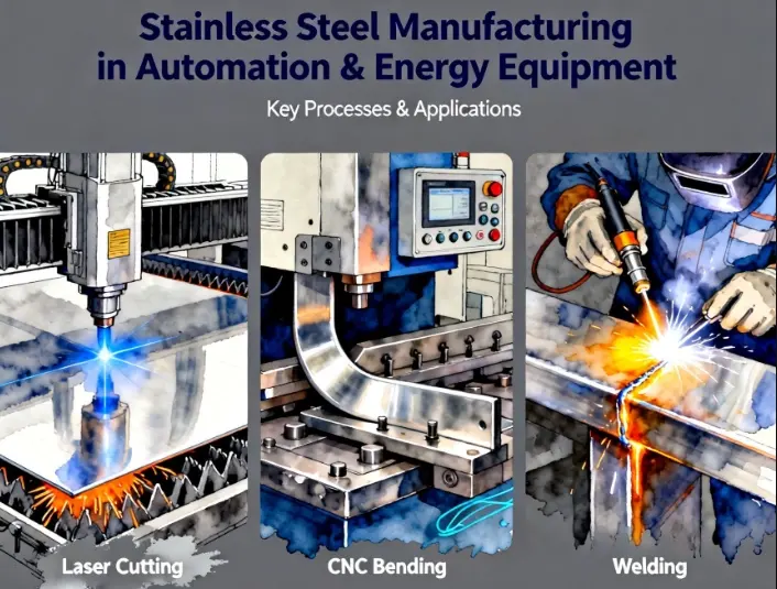
Stainless Steel Sheet Metal Fabrication Services for Automation and Energy Equipment
Tan161130.2025-11-05T07:25:22+00:00November 5, 2025|
Understanding Stainless Steel Sheet Metal Fabrication for Automation and Energy Equipment Stainless steel sheet metal fabrication integrates precision [...]
Hello world!
Tan161130.2025-10-16T02:19:56+00:00October 16, 2025|
Welcome to WordPress. This is your first post. Edit or delete it, then start writing!


