
A single tolerance callout on a sheet metal drawing can add 20–40% to the quoted price — or save the same amount when it is properly optimized. For OEM engineers and procurement teams, the question is not whether tolerance optimization works. The question is whether the investment makes sense for your specific parts, your production volume, and your current project stage.
This article breaks down what tolerance optimization actually involves in sheet metal fabrication, what it costs, what it can save, and — most importantly — how to decide whether it is worth pursuing for your next order.
What Tolerance Optimization Actually Means for Sheet Metal Parts
Tolerance optimization is the process of reviewing every dimension on a drawing, identifying which tolerances are functionally necessary, and relaxing the ones that are not. It is not a blanket loosening of specs. It is a targeted reallocation: tighter where function demands it, standard everywhere else.
The term is often confused with two related but distinct activities. A DFM review (design for manufacturability) looks at the entire part — bend radii, hole placement, material choice, weld access — and flags features that are difficult or expensive to produce. Tolerance optimization is narrower: it focuses specifically on whether the dimensional and geometric callouts on the drawing are justified by the part’s function. A tolerance stack-up analysis calculates how variations across multiple parts combine in an assembly. Tolerance optimization may use stack-up results, but its scope extends to every dimension on the drawing, not just the ones in a critical assembly chain.
Why Sheet Metal Tolerances Behave Differently from Machined or Molded Parts
In CNC machining, the cutting tool follows a programmed path and can hold ±0.005″ (0.13 mm) or tighter with relative consistency. In injection molding, the die is fixed and produces near-identical parts shot after shot. Sheet metal fabrication is different.
Laser cutting can hold ±0.005″ (0.13 mm) on profile dimensions, but bend tolerances are inherently less precise — typically ±0.5° on angle and ±0.010″ (0.25 mm) on flange length for standard press-brake work. Each bend introduces springback, and springback varies with material, grain direction, tooling wear, and ambient temperature. When a part has multiple bends, cumulative error across those bends can reach ±0.020–0.030″ (0.5–0.75 mm) without any individual dimension being out of spec.
This means that specifying a ±0.005″ tolerance on a feature that depends on three bends is not just expensive — it may be physically unachievable without secondary operations like machining or iterative hand-fitting. Understanding this manufacturing reality is the starting point for any meaningful tolerance discussion.
Where Over-Tolerancing Hides the Cost in a Sheet Metal Quote
When a fabricator receives a drawing with tight tolerances on every dimension, the quote reflects risk. The fabricator does not know which tolerances are critical and which were copied from a previous design or tightened “just to be safe.” So they price for the worst case. Here is where that cost actually lands.
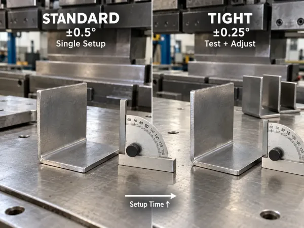
Over-tolerancing can increase setup, inspection, scrap and secondary processing costs.
Laser Cutting: Tighter Tolerances Slow Feed Rates and Raise Scrap on Thin Gauges
Standard laser cutting tolerances for sheet metal are ±0.005″ (0.13 mm). When a drawing calls for ±0.002″ (0.05 mm) on cut features, the operator must reduce feed rate, use finer gas pressure settings, and run more frequent calibration checks. On thin gauges (under 1 mm), tighter tolerances also increase the risk of thermal distortion — the heat-affected zone becomes a larger percentage of the feature size, and scrap rates climb.
The cost impact is not dramatic for a single feature, but it compounds. A part with 30 holes all specified at ±0.002″ instead of ±0.005″ will take longer to cut and reject more parts during inspection than a part where only the 4 mounting holes carry the tighter spec.
Bending: Angular and Flange-Length Tolerances Drive Press-Brake Setup Time
Bending is where tolerance costs escalate most visibly in sheet metal. A ±0.5° angular tolerance is achievable with standard tooling and a single setup. Tighten that to ±0.25°, and the operator must run test bends, measure with a protractor or CMM, adjust the ram depth, and repeat — often two or three iterations before the first good part. On a low-volume run of 50 parts, that setup time can represent 30–50% of the total bending cost.
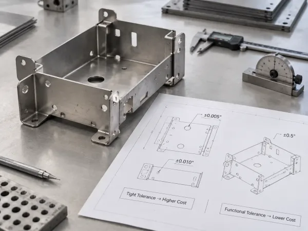
Tighter bend tolerances often require test bends, additional measurement and repeated setup adjustments.
Flange-length tolerances follow the same pattern. ±0.010″ is standard; ±0.005″ requires careful back-gauge positioning and may need a dedicated fixture if the flange is short or the material is thick. The cost difference between these two tolerance levels on a single bend can be 0.50–2.00 per part — multiplied across hundreds of parts and multiple bends, it adds up quickly.
Welding and Assembly: Post-Form Distortion Makes Some Tight Tolerances Physically Unachievable
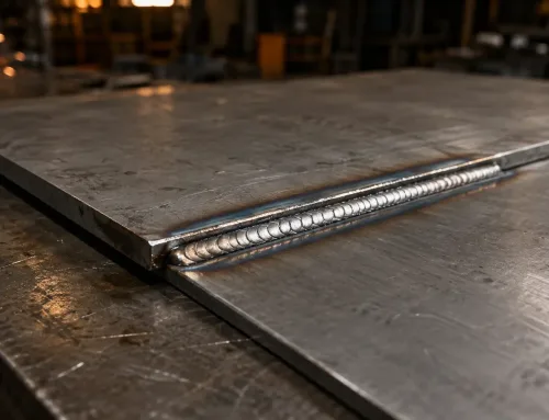
Sheet metal parts that require welding face an additional challenge: heat distortion. A TIG weld on 1.5 mm stainless steel can introduce 0.5–1.0 mm of localized distortion. If the drawing specifies a ±0.010″ tolerance on a dimension that crosses a weld zone, the part may be impossible to produce without post-weld machining or fixturing that holds the part in a constrained state during welding — both of which add significant cost.
This is one of the most common sources of conflict between design intent and manufacturing reality. The engineer specifies a tight tolerance based on the CAD model’s nominal geometry. The fabricator knows that welding will move the material beyond that tolerance. The result is either a high quote (reflecting the cost of fixturing and rework) or a request for clarification that delays the project.
Inspection: Every Extra Critical Dimension Adds CMM Time and Fixture Cost
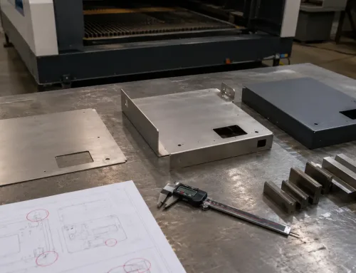
Each dimension marked as critical on a drawing must be verified. For sheet metal parts, verification typically means CMM (coordinate measuring machine) inspection or optical comparison. A part with 5 critical dimensions might take 10–15 minutes to inspect. A part with 20 critical dimensions — where 15 of them are non-functional “insurance” tolerances — can take 45–60 minutes.
At typical CMM inspection rates of **75–**150/hour, that extra 30–45 minutes adds 37–112 per part in inspection cost alone. For a batch of 200 parts, that is 7,400–22,400 spent verifying dimensions that do not affect form, fit, or function.
What Tolerance Optimization Consulting Actually Costs
The cost of tolerance optimization depends on who does it, how many parts are involved, and how the engagement is structured.
Hourly Rate Ranges
Offshore GD&T and tolerance-analysis specialists (typically in India, Eastern Europe, or Southeast Asia) charge **15–**35/hour. Domestic consultants in the US, Canada, or Western Europe charge **150–**350/hour, with rates reflecting the complexity of the analysis and the industry (aerospace and medical command the highest rates).
For most OEM sheet metal projects, the offshore rate range is relevant for straightforward tolerance reviews, while domestic consultants are better suited for complex assemblies with safety-critical interfaces.
Project-Based Pricing
A typical tolerance audit of 10–50 sheet metal parts — covering dimension classification, stack-up analysis on critical fits, and recommendations for relaxation — runs **3,000–**15,000 depending on complexity and the consultant’s location. Larger audits involving 100+ parts or multi-assembly systems can reach **25,000–**50,000.
The key metric is cost per part. At $5,000 for a 30-part audit, you are paying roughly $167 per part for a review that can save 0.50–5.00 per part in production — a return that pays back within the first production run for most mid-volume orders.
The Hidden Cost: What Your Supplier Charges When They Fix Tolerance Problems for You
When a fabricator receives a drawing with over-toleranced dimensions, they do not simply relax the tolerances and re-quote. They flag the issues, request clarification, wait for a response, and re-quote — a cycle that typically adds 3–7 business days to the quoting process. If the fabricator quotes to the drawing as-is (without flagging the issue), the quote includes a risk premium that reflects their expectation of rework, higher scrap, or longer setup time.
In practice, many fabricators absorb some of this cost by suggesting tolerance relaxations during the DFM review. But that DFM feedback is free only in the sense that the fabricator does not charge for it directly. The cost is embedded in the relationship: a supplier who repeatedly receives over-toleranced drawings will eventually prioritize customers whose drawings are cleaner.
A Decision Framework — When Is Tolerance Optimization Worth the Investment?
Not every project benefits equally from tolerance optimization. The ROI depends on four factors.
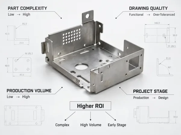
Tolerance optimization delivers the strongest ROI on complex, higher-volume parts early in the project.
Factor 1 — Part Complexity: How Many Critical Fits and Mating Interfaces Does the Drawing Have?
A simple bracket with 3 holes and 1 bend has very few dimensions that could be over-toleranced. The cost savings from optimization are small, and the consulting investment may not pay back. An enclosure with 40+ features, multiple bends, welded seams, and 10 mounting interfaces that mate with another assembly has far more room for tolerance to drive cost — and far more room for optimization to save money.
Rule of thumb: If your part has fewer than 10 dimensions that could plausibly be critical to function, tolerance optimization is unlikely to deliver meaningful savings. If it has 20 or more, the math usually works.
Factor 2 — Current Drawing Quality: Are Tolerances Function-Based or “Insurance Tolerances”?
Some drawings carry tolerances that were carefully derived from assembly requirements, stack-up analyses, and functional testing. Others carry tolerances that were copied from a similar part, specified at the tightest level the CAD software offered, or tightened after a past quality incident that had nothing to do with the current design.
If your drawing falls into the second category — and industry experience suggests that 60–80% of tolerances on a typical engineering drawing are tighter than functional requirements demand — the savings potential is significant. A tolerance audit can identify which callouts are justified and which are costing money without delivering value.
Factor 3 — Production Volume: Low-Volume vs. High-Volume Changes the Cost-Per-Part Math
For a prototype run of 10 parts, the absolute savings from tolerance optimization are small. Relaxing a tolerance might save $2 per part — $20 total. The consulting cost will not pay back.
For a production run of 5,000 parts, the same $2 per part savings becomes $10,000. For a product with an annual volume of 20,000 parts and a 5-year lifecycle, it becomes $200,000. The consulting investment of $5,000–$15,000 looks different at each volume level.
The crossover point: Most tolerance optimization investments pay back within the first production run when annual volume exceeds 500–1,000 parts. Below that, the ROI is marginal unless the parts are highly complex or the current tolerances are dramatically over-specified.
Factor 4 — Project Stage: Design, Quoting, Prototype, or Production — Where You Are Determines the ROI
Tolerance optimization delivers the highest ROI when done before the first quote is sent. At the design stage, changing a tolerance on a drawing takes minutes and costs nothing. At the quoting stage, it can prevent a risk premium from being added to the quote. At the prototype stage, it can eliminate the need for rework or secondary operations. At the production stage, it can still reduce inspection cost and scrap, but the tooling and process decisions are already locked in, and the savings are smaller.
The 10× rule applies here: a tolerance issue that costs $1 to fix in design costs $10 to fix in quoting, $100 to fix in prototype, and $1,000+ to fix in production.
What a Sheet Metal Tolerance Audit Delivers
A structured tolerance audit follows a defined sequence. Here is what the process looks like when applied to sheet metal parts.
Step 1 — Classify Every Dimension: Critical-to-Function vs. Non-Critical
The auditor reviews every dimension on the drawing and classifies it as CTF (critical-to-function) — meaning it directly affects fit, sealing, alignment, or structural performance — or non-critical, meaning it can be relaxed to standard process tolerances without affecting how the part works.
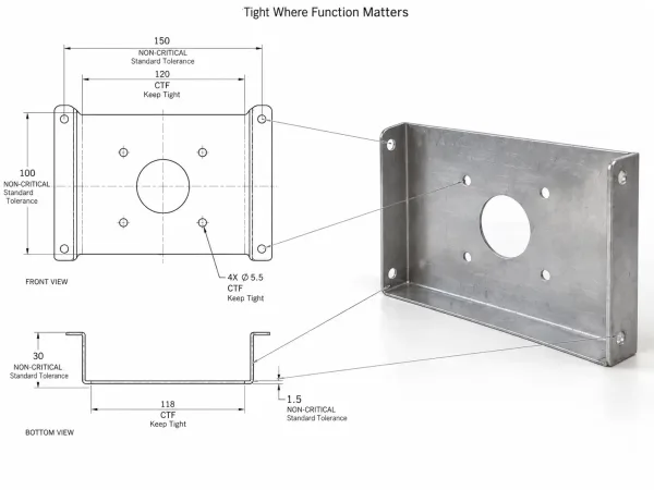
Tolerance optimization keeps critical functional dimensions tight while relaxing non-critical dimensions.
In practice, CTF dimensions typically represent 5–15% of all dimensions on a sheet metal drawing. The rest are clearance holes, trim edges, non-mating surfaces, and features whose tolerances were inherited rather than derived.
Step 2 — Run Tolerance Stack-Ups on Mating Interfaces
For every CTF dimension that participates in an assembly, the auditor runs a tolerance stack-up analysis — either worst-case (for safety-critical interfaces) or statistical (RSS or Monte Carlo, for most commercial applications). This determines whether the specified tolerance is necessary, sufficient, or unnecessarily tight given the tolerance budget of the assembly.
A common finding: a mounting hole pattern specified at ±0.005″ when the mating part has ±0.010″ clearance holes. The stack-up shows that ±0.010″ on the mounting holes would still achieve the required fit — and cost significantly less to produce.
Step 3 — Match Tolerances to Process Capability
The auditor maps each CTF tolerance against the process capability of the intended manufacturing method. For sheet metal, the reference points are:
| Process | Typical Capability | Tighter Requires |
|---|---|---|
| Laser cutting (profile) | ±0.005″ (0.13 mm) | Reduced feed rate, more scrap |
| Punching | ±0.003″ (0.08 mm) | Tooling condition, punch-die clearance |
| Bending (angle) | ±0.5° | Iterative setup, test bends |
| Bending (flange length) | ±0.010″ (0.25 mm) | Dedicated fixture, CMM verification |
| Welding (post-form position) | ±0.020–0.030″ (0.5–0.75 mm) | Welding fixture, post-weld machining |
| PEM hardware installation | ±0.010″ (0.25 mm) | Manual alignment, fixture |
Tolerances that fall within the process’s natural capability are straightforward to produce. Tolerances that require capability beyond the standard range carry a cost premium that should be justified by function.
Step 4 — Deliver the Optimized Drawing
The final deliverable is a revised drawing (or a marked-up review package) with:
- CTF dimensions retained with their original (or refined) tolerances
- Non-critical dimensions relaxed to ISO 2768-m (medium) general tolerances or process-standard ranges
- GD&T callouts added or corrected where they improve communication of functional intent
- A summary of changes with cost impact estimates
The goal is a drawing that communicates exactly what matters and nothing more — giving the fabricator the flexibility to produce the part efficiently while protecting every dimension that affects performance.
How to Push Tolerance Optimization Through Your Supplier Relationship
Even when the engineering team understands the value of tolerance optimization, implementation often stalls at the supplier interface. Here is how to make it work in practice.
What to Include in Your RFQ to Get Tolerance Feedback Early
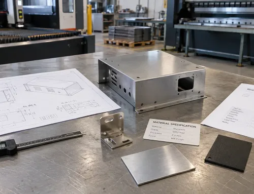
Most fabricators will flag obvious tolerance issues during quoting — but only if the RFQ gives them enough context to do so. Include the following with your drawing package:
- Assembly context: a note or separate drawing showing how this part mates with adjacent components
- Critical dimensions list: explicitly mark which 3–5 dimensions are CTF and why
- Quantity and annual volume: fabricators price tolerance risk differently for 50 parts vs. 5,000
- Finish and material: these affect achievable tolerances and should be confirmed before quoting
A drawing with 40 tight dimensions and no indication of which ones matter forces the fabricator to either quote high (assuming all are critical) or spend time asking questions that delay the quote by days.
How to Read a Supplier’s DFM Comments on Tolerances
When a fabricator suggests relaxing a tolerance, they are not trying to cut corners. They are telling you that the specified tolerance adds cost — and that, based on their experience producing similar parts, a wider tolerance would be functionally equivalent.
The right response is not “hold to print” by default. It is to ask: “What is the functional risk if this tolerance is relaxed to [their suggestion]?” If the fabricator can explain why the relaxed tolerance still meets the assembly requirement, accept it. If they cannot, hold the tolerance — but understand that you are paying for precision that may not be necessary.
When to Accept the Supplier’s Suggestion and When to Push Back
Accept the suggestion when:
- The fabricator points to a specific dimensional relationship (e.g., “this hole mates with a clearance slot on the other part — ±0.010″ is sufficient”)
- The tolerance was inherited from a previous design without specific functional justification
- The stack-up analysis supports the relaxed value
Push back when:
- The dimension controls a sealing interface, a press-fit, or a safety-critical alignment
- The fabricator’s suggestion is based on their process limitations rather than your functional requirements (in which case, the solution may be a different manufacturing method, not a relaxed tolerance)
- You have test data or field failure history that validates the original tolerance
The goal is a collaborative conversation, not a negotiation. The best outcomes happen when the OEM shares functional context and the fabricator shares process context — and both sides use that information to find the tolerance that is tight enough and not tighter.
FAQs