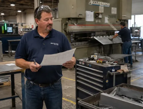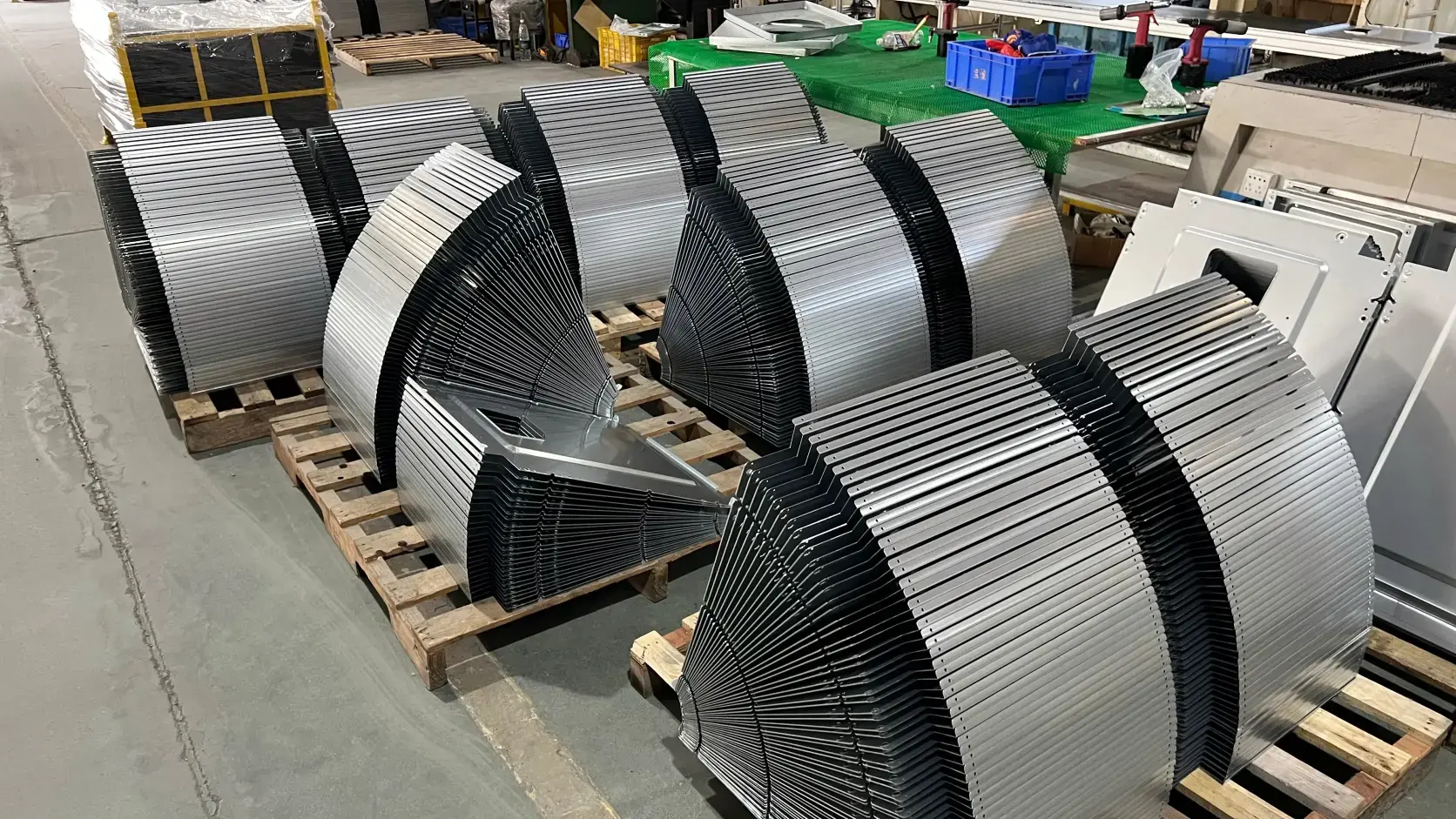

A powder-coated enclosure arrives at your facility. The color matches the spec, the dimensions look right — until you try to install the mounting hardware. The holes are 1.2 mm off from the mating bracket. The root cause is not a programming error or a machine fault. It is an operation sequence issue: the part was bent before the holes were reamed, and each bend introduced positional drift that nobody caught until assembly. The entire batch needs rework, and the delivery date just slipped by two weeks.
Scenarios like this are more common than most buyers realize. In sheet metal fabrication, the order in which operations are performed — cutting, bending, welding, surface finishing, inspection — is not a matter of shop-floor preference. It is a chain of engineering dependencies where each step’s output becomes the next step’s input. When that chain is broken, defects do not appear immediately. They surface downstream, often after the most expensive operations have already been completed.
This glossary entry explains what operation sequence means in a manufacturing routing, why the specific order matters for sheet metal parts, and what happens when it is wrong.
What Operation Sequence Actually Means in a Manufacturing Routing
In a manufacturing route sheet — the document that defines how a part moves through the shop floor — each fabrication or assembly step is assigned a sequence number. This number determines the order in which operations are performed. For example, a simple bracket routing might list Operation 10 as laser cutting, Operation 20 as deburring, Operation 30 as bending, and Operation 40 as powder coating.
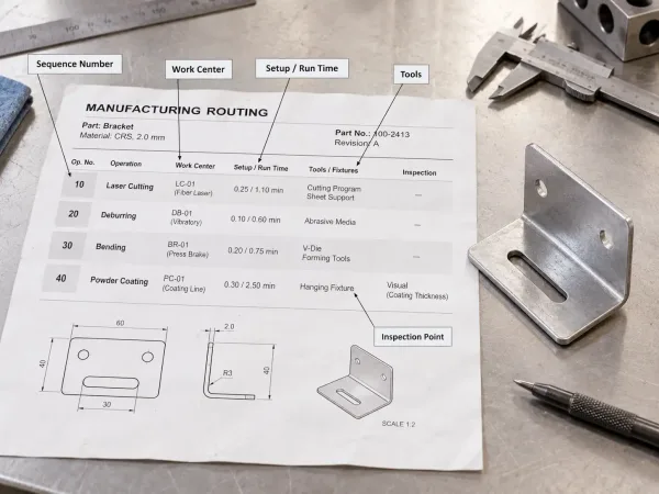
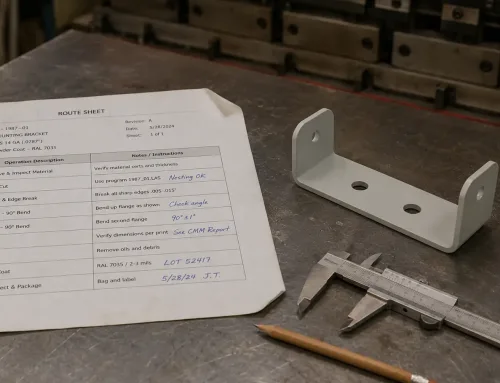
A manufacturing routing showing sequence numbers that define the order of sheet metal fabrication operations.
The operation sequence is a property within the routing, not a separate document. It works alongside other routing data: the work center (which machine), the setup and run time estimates, the tools required, and any in-process inspection points. Together, these fields tell the shop floor how to turn a flat drawing into a finished part.
It is worth distinguishing operation sequence from related terms. A bill of materials (BOM) defines what goes into a part — material type, thickness, fasteners — but says nothing about the order of fabrication steps. A work order authorizes production of a specific quantity and links to the routing, but the routing itself holds the sequence logic. The operation sequence number is the ordering mechanism that makes the routing executable rather than a flat list of tasks.
The Typical Operation Sequence for a Sheet Metal Part
For most sheet metal parts, the sheet metal production workflow follows a sequence dictated by physics and geometry rather than convention:
Laser or plasma cutting → Deburring → Forming or bending → Welding → Grinding or fitting → Surface finishing (paint, powder coat, or anodizing) → Final inspection → Packing
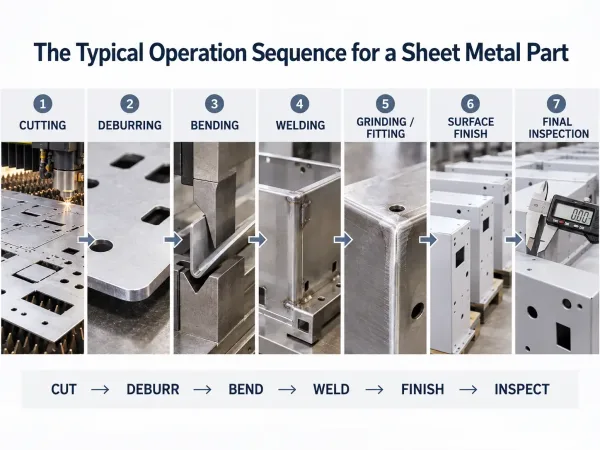
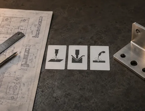
The standard sheet metal fabrication sequence from cutting and deburring through forming, finishing, and inspection.
This order exists because each operation depends on the output of the one before it. Cutting produces the flat pattern with all holes and contours. Deburring removes sharp edges and dross so that bending tools are not damaged and formed surfaces are clean. Bending transforms the flat pattern into a three-dimensional geometry. Welding joins separate components into an assembly. Grinding cleans up weld seams. Surface finishing applies a protective or decorative coating to the completed geometry. Inspection verifies the finished part against the drawing.
The dependency chain is not arbitrary. If you bend before cutting all holes, the holes cannot be reamed in the flat state — they must be drilled after forming, which is slower, less accurate, and more expensive. If you apply powder coat before welding, the coating in the weld zone will burn off, leaving bare metal that corrodes. If you skip metal deburring before bending, burrs can score the die surface and imprint defects into every subsequent part.
There are exceptions. Some designs require operations to be interleaved — for instance, a part that needs partial bending before certain holes can be punched due to access constraints. But these exceptions are deliberate engineering decisions documented in the routing, not accidental deviations.
What Happens When the Sequence Is Wrong
When operations are performed out of order, the consequences fall into three categories: tolerance accumulation, surface contamination, and cost amplification.
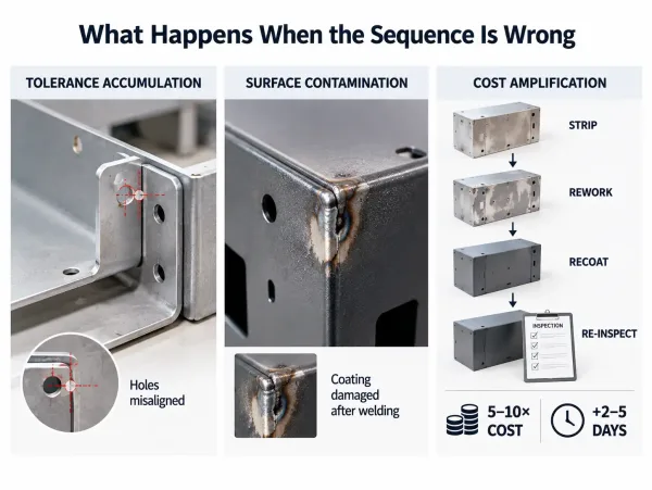
Three common consequences of incorrect sheet metal operation sequence: tolerance drift, surface damage, and increased rework cost.
Tolerance Accumulation
Every time a part is repositioned — moved from one fixture to another, flipped, or rotated — small positional errors are introduced. In a correctly sequenced routing, these errors are managed because each operation references features that were created in a prior, stable setup. When the sequence is broken, tolerances stack in ways the drawing did not anticipate.
A common example: holes are laser-cut in the flat pattern, then the part is bent. If the bend sequence is wrong — say, the long flange is bent before the short flange — the hole positions relative to the formed edges shift by 0.3–0.8 mm depending on material thickness and bend radius. On a single prototype, this may be tolerable. Across a batch of 500 parts, it means the holes will not align with the mating bracket, and the entire lot fails incoming inspection.
Surface Contamination
Surface finishing operations — powder coating, anodizing, e-coating — are designed to be the last steps before inspection and packing. They assume the underlying geometry is complete and stable. When welding or grinding is performed after surface finish, the coating in the affected area is destroyed.
This is not a cosmetic issue alone. Powder coat over weld spatter creates a weak adhesion point where moisture penetrates, initiating corrosion under the coating. Anodizing over an un-deburred edge produces uneven oxide thickness, which shows as color variation on visible surfaces. In both cases, the fix requires stripping the entire coating, re-processing the part, and re-coating — a cycle that can double the per-part cost and add days to the lead time.
Cost Amplification
The financial impact of a sequence error is not linear — it is exponential relative to how far downstream the error is discovered. A missing deburr caught before bending costs seconds to fix. The same missing deburr caught after powder coat requires:
- Stripping the coating (chemical or mechanical)
- Deburring the part
- Re-applying surface treatment
- Re-inspecting the part
This rework loop typically costs 5–10× the original operation cost and adds 2–5 days to the delivery schedule. For low-volume orders where NRE and setup costs are already amortized across few parts, the per-unit rework cost can exceed the original unit price.
The worst-case scenario is a sequence error that is not caught until assembly at the customer’s facility. At that point, the cost includes return shipping, expedited replacement production, and — most damaging — lost confidence in the supplier’s process control.
When Parallel Operations Are Acceptable
Not every operation must wait for the previous one to finish. The key question is whether operation B requires the physical output of operation A, or whether both operations work on independent features or sub-assemblies.
True dependencies (must be sequential): You cannot bend a part before cutting its holes in the flat pattern, because the holes reference the flat geometry. You cannot weld before all components are formed, because the weld joint geometry depends on the mating edges.
False dependencies (can be parallel): If a sheet metal enclosure consists of a main body and a separate mounting bracket, the bracket can be cut, bent, and deburred while the main body is still being welded. These are independent sub-assemblies that only need to come together at the final assembly step.
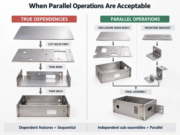
A comparison of operations that must remain sequential and independent sheet metal sub-assemblies that can run in parallel.
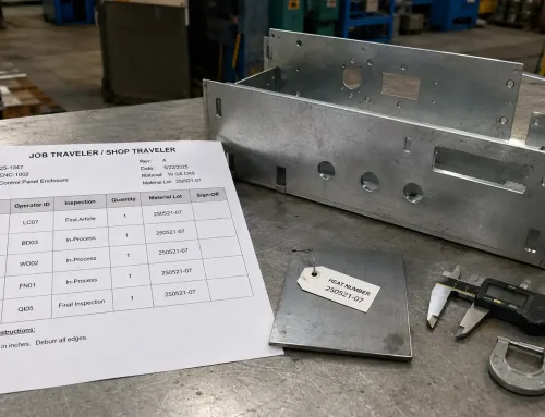
Shop floors that understand this distinction can run parallel operations on independent sub-assemblies without compromising quality. The routing should clearly document which operations have hard dependencies and which can be dispatched independently, while the job traveler carries that approved sequence through actual shop-floor execution. If your routing shows a strictly linear sequence for a multi-component assembly, it is worth asking whether the manufacturer has considered parallel processing — not because parallel is always better, but because it can reduce lead time without adding risk.
How to Review Operation Sequence on a Routing or Quote
When you receive a routing summary with a quote, or when your engineering team reviews a manufacturer’s process plan, the operation sequence deserves specific attention. Four checks can catch most problems before production starts:
- Are all hole and contour operations complete before forming? In most sheet metal parts, holes should be created in the flat pattern (by laser, punch, or drill) before bending. Post-form drilling is acceptable only when the drawing explicitly requires it or when geometric constraints prevent flat-pattern access.
- Is surface finish the last step before inspection? Powder coat, anodize, paint, and e-coat should follow all welding, grinding, and fitting operations. If surface finish appears before welding in the sequence, the coating in the weld zone will be destroyed.
- Are deburring operations placed after cutting, not before? This sounds obvious, but in routings with many steps, deburr operations are sometimes listed generically and not tied to the correct predecessor. A deburr step that precedes the cutting step it is meant to clean up is a routing error.
- Does the sequence account for sub-assembly logic? For multi-component parts, check whether the routing distinguishes between sub-assembly fabrication sequences and the final assembly sequence. A flat, linear routing for a complex welded assembly may indicate that parallel processing opportunities — or dependency risks — have not been analyzed.
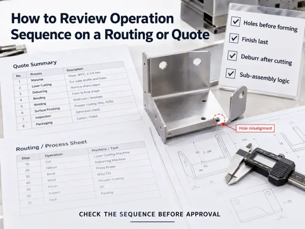
Four practical checks for reviewing sheet metal operation sequence before approving production.
If any of these checks reveal a gap, request a revised routing before approving production. Changing the sequence after cutting has begun is possible but expensive, because it may require re-fixturing, re-programming, or scrapping partially processed parts.
Key Takeaways
- Operation sequence is the ordering of fabrication and assembly steps within a manufacturing routing — it determines how a part moves through the shop floor.
- In sheet metal manufacturing, the standard sequence (cut → deburr → bend → weld → grind → surface finish → inspect) exists because each step’s output is the next step’s physical input prerequisite.
- Sequence errors do not fail fast — they accumulate as tolerance drift, surface contamination, or rework costs that multiply with each downstream operation.
- Parallel operations are acceptable for independent sub-assemblies, but only when the routing clearly documents which steps have hard dependencies.
- Buyers and engineers should review operation sequence on every routing or quote, checking for four common gaps before approving production.
FAQ