
A revision is not just a letter stamped in the corner of a drawing. It is a controlled record of what changed, when, and who approved it — and for anyone ordering custom parts, it is the only reliable way to confirm that a supplier is working from the correct design.
What Drawing Revision Actually Means
When a 2D engineering drawing is first released, it is issued at an initial revision. Every subsequent change — whether it corrects a dimension, updates a material callout, or adds a new feature — must be formally incorporated as a new revision. The drawing number stays the same; the revision changes.
A drawing revision is a formally controlled update to a released engineering drawing, identified by a revision code and recorded through an established change process. It documents changes to the product definition: dimensions, tolerances, materials, notes, or configuration details.
This distinction matters. A markup on a shop print, a redline emailed to a colleague, or a verbal instruction to “use the newer version” — none of these are drawing revisions. A revision only exists once it has been incorporated into the drawing, assigned a revision code, and released through the formal document control process. Until that happens, the previous revision remains the governing document.
For a buyer or engineer sending a drawing to a sheet metal supplier, the revision code on the title block is the first thing the supplier checks. It tells them whether they are looking at the same version that was used for the last order, or whether something has changed that affects their tooling, programming, or inspection.
What Goes into the Revision Table
The revision table — sometimes called the revision block or record of revisions — is a small table on the drawing that records every change made after initial release. Its location varies by standard: ASME-format sheets typically place it in the upper right corner, while ISO-format sheets place it near the title block.
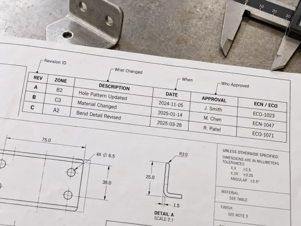
Revision table showing the key fields used to document and trace engineering drawing changes.
A well-structured revision table contains the following fields:
| Field | What It Records | Why It Matters |
|---|---|---|
| Revision identifier | The letter or number assigned to this revision (e.g., A, B, C or 1, 2, 3) | Unique reference that ties the drawing to a specific state of the design |
| Zone or grid reference | The area on the sheet where the change was made | Allows someone holding the previous issue to locate the change without re-reading the entire drawing |
| Description of change | A brief summary of what was modified | Tells the reader what is different and why — a field that says only “revised” has recorded nothing |
| Date | When the revision was accepted | Establishes the timeline and helps resolve disputes about which version was current at a given point |
| Approval | Who checked and approved the change | Provides accountability and confirms the change went through the formal review process |
| ECN / ECO number | Reference to the Engineering Change Notice or Engineering Change Order that authorized the revision | Ties the drawing to the broader change control system — this is the field that connects the drawing to a workflow, not just to another drawing |
Not every organization includes all six fields. Some add columns for the drafter, the person who checked the change, or delivery information. But the core — identifier, description, date, and approval — should always be present. A revision table with gaps is a revision table that cannot answer the question: what changed, and who agreed to it?
How Revision Letters and Numbers Are Assigned
There is no single universal numbering system. Two broad approaches exist — alphabetical and numerical — and the choice depends on the standard the organization follows.
The ASME Y14.35 Alphabetical Sequence
The most widely referenced system is defined by ASME Y14.35, Revision of Engineering Drawings and Associated Documents. It specifies an alphabetical sequence with one important rule: six letters are omitted.
The usable alphabet is: A, B, C, D, E, F, G, H, J, K, L, M, N, P, R, T, U, V, W, Y — twenty letters, not twenty-six.
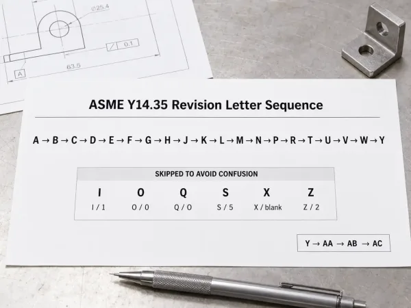
ASME drawing revision sequence showing the usable letters and the six letters excluded to avoid confusion.
The letters I, O, Q, S, X, and Z are excluded because they are easily confused with other characters on a printed or scanned drawing:
- I reads as 1
- O reads as 0
- Q reads as O
- S reads as 5
- X reads as a blank field someone forgot to fill in
- Z reads as 2
When the single-letter sequence is exhausted after Y, the system continues with double letters: AA, AB, AC … AY, then BA, BB … YY. Revisions beyond YY continue to three letters (AAA, AAB, and so on), though in practice most organizations issue a new drawing number before reaching that point.
Numerical Sequences
Many organizations, particularly those following ISO practice, use numbers instead: 0, 1, 2, 3, … or starting from 1. Some organizations use a hybrid approach — letters during design and construction phases (A, B, C, D), then numbers once the drawing is issued for as-built or operational use (1, 2, 3, …).
The Initial Revision
The first release of a drawing carries its own revision identifier. Common practices include:
- Dash (–): Used under ASME Y14.35 to indicate the original release before any revision has been made
- 0 or 1: Used in numerical schemes — whether 0 or 1 is the starting point depends on the organization’s documented convention
- A: Some organizations treat the first checked-and-approved issue as Rev A, with no separate “initial release” state
The important point is that the convention must be documented and consistent within the organization. A blank revision field on a drawing is immediately visible as uncontrolled.
Where the Revision Appears on the Drawing
Revision information shows up in three places on an engineering drawing, each serving a different purpose.
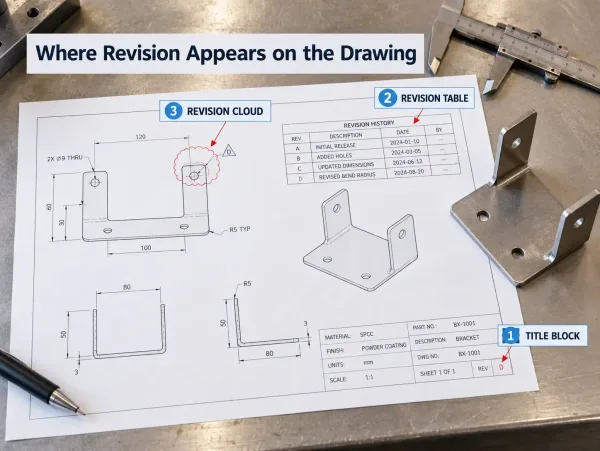
Engineering drawing highlighting the three main locations where revision information appears.
The title block. The title block contains a revision field that displays the current revision level. This is the single most visible indicator of which version a drawing represents. When a supplier opens a drawing, the revision field in the title block is the first thing they check.
The revision table. Located in the upper right corner (ASME) or near the title block (ISO), the revision table provides the full history of changes. It records what was modified at each revision, when, and by whom. The title block tells you which revision you are looking at; the revision table tells you what changed at each step.
Revision marks on the drawing views. When a specific area of the drawing changes, it is marked with a revision cloud — a rounded, bump-edged shape drawn around the affected region — and a revision symbol, typically a small triangle containing the revision letter or number. These marks are connected to the revision table entry, so a reader can go directly to the area of the drawing that was modified.
On large sheets that use zoning (grid coordinates along the margins, such as C/7 or B-3), the revision table entry may include a zone reference. This makes it straightforward to locate the change: the table says “revised at C/7,” and you look at zone C/7 on the sheet.
How to Confirm the Supplier Has the Correct Revision
For a buyer ordering custom sheet metal parts, the most common source of wrong-revision errors is not a failure of the supplier’s document control system — it is a gap in the communication between buyer and supplier at the point of order.
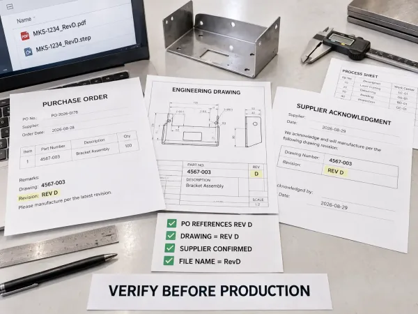
Procurement review showing how buyers confirm the correct drawing revision before manufacturing begins.
The most effective way to close that gap is to make the revision explicit at every stage of the transaction:
State the revision on the purchase order. The PO should reference not only the drawing number but also the specific revision level: “Drawing 4567-003, Rev C.” This allows the supplier’s manufacturing work order to carry the correct drawing revision into production. If the PO references only the drawing number, the supplier has no contractual basis for choosing one revision over another.
Require written acknowledgment. Add a line to your PO or standing operating procedure: “Supplier shall confirm receipt of the current drawing revision in writing before beginning production.” A useful acknowledgment includes:
- Drawing number and active revision confirmed
- Date the revision was received
- Whether the change affects tooling, process, inspection, material, or inventory
- The first lot or order affected
- Any technical clarifications or required deviations
A weak acknowledgment says “received, thanks.” A useful one gives the buyer decision-quality information.
Attach the complete sheet metal fabrication drawing package — never just the changed page. A machinist should be able to manufacture the part from the single document you send, without needing to piece together old and new pages.
Name files clearly. Use the part number and revision in the filename: “MKS-1234_RevC.pdf” and “MKS-1234_RevC.step.” Avoid filenames that include “final,” “updated,” or dates — they create version confusion.
Maintain a revision log. For repeat orders, keep a simple table tracking every revision sent to each supplier:
| Part Number | Revision | Date Sent | Supplier Acknowledgment |
|---|---|---|---|
| 4567-003 | Rev C | 2026-07-15 | 2026-07-16 |
| 4567-003 | Rev D | 2026-08-20 | 2026-08-21 |
This log is your audit trail when investigating a wrong-revision event and is required for regulatory traceability in medical device and aerospace programs.
What Happens When Revision Control Fails
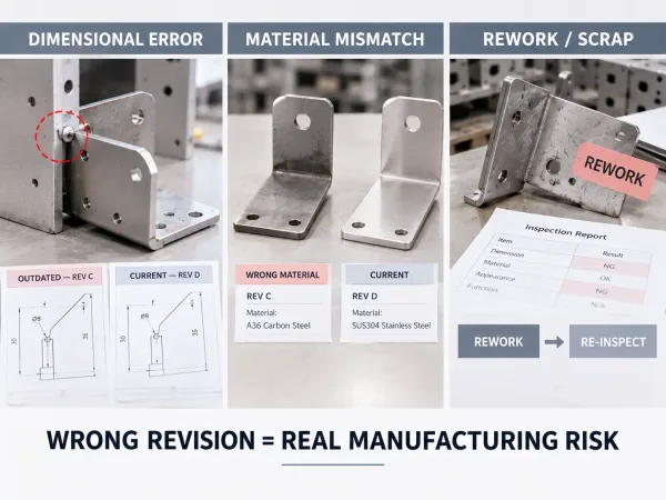
Comparison showing dimensional errors, material mismatches, and rework caused by manufacturing from an outdated drawing revision.
When a supplier manufactures to an outdated revision, the consequences range from minor to severe:
- Dimensional errors. A changed hole pattern or bend radius produces parts that do not fit the assembly.
- Material mismatches. A revised material callout goes unnoticed, and the supplier orders or cuts the wrong stock.
- Inspection failures. Quality checks are performed against the current revision’s requirements, but the part was made to the previous revision — leading to false rejections or, worse, false approvals.
- Rework and scrap. Parts already in production or finished goods may need to be reworked, scrapped, or shipped under a concession, adding cost and delaying the schedule.
- Traceability gaps. In regulated industries, the inability to link a shipped part to a specific drawing revision can trigger audit findings or customer complaints.
The common thread in all of these scenarios is that someone — buyer, supplier, or both — was working from a different version of the same drawing. The revision system exists to prevent that. When it fails, the failure is almost always in the communication, not in the system itself.
Key Takeaways
- A drawing revision is a formally controlled update to a released drawing, not a casual version label.
- The revision table records what changed, when, and who approved it — every field serves a traceability purpose.
- ASME Y14.35 defines a 20-letter alphabetical sequence that skips I, O, Q, S, X, and Z to avoid confusion on printed drawings.
- Revision information appears in three places: the title block (current level), the revision table (history), and revision marks on the drawing views (location of changes).
- Confirming the supplier’s revision requires explicit PO references, written acknowledgment, and clear file naming — not just an assumption that they have the latest version.
FAQ